Chapter 13 Magnetic Effects of Electric Current Class 10 Science Important Questions with Answers PDF will help you in scoring more marks. This consists of 1 mark Questions, 3 Mark Numericals Questions, 5 Marks Numerical Questions and previous year questions from Chemical Reactions and Equations Chapter.
Magnetic Effects of Electric Current Class 10 Important Questions and Answers Science Chapter 13
Very Short Answer Questions
Based on magnet and magnetic field
Question 1.
Identify the poles of a magnet in the figure.
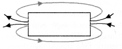
Answer:

More Resources
- Previous Year Question Papers for CBSE Class 10 Science
- NCERT Solutions for Class 10 Science
- NCERT Exemplar Solutions for Class 10 Science
- Value Based Questions in Science for Class 10
- HOTS Questions for Class 10 Science
Question 2.
What is the direction of magnetic field lines outside a bar magnet ? (CBSE 2010, 2011)
Answer:
From North pole to South pole.
Question 3.
What does crowding of magnetic field lines indicate ? (CBSE 2010, 2011)
Or
What does the degree of closeness of magnetic field lines near the poles signify ? (CBSE 2012)
Answer:
Crowding of magnetic field lines indicates that magnetic field in that region is strong.
Question 4.
At what place of the magnet are the magnetic field lines denser ? [CBSE (All India) 2007]
Answer:
Near the poles of the magnet.
Question 5.
What is meant by magnetic field ? [CBSE (Delhi) 2007, 2009, 2014]
Answer:
The space around a magnet or current carrying conductor within which its influence can be felt by a magnetic substance like iron is called magnetic field.
Question 6.
How is the direction of magnetic field at a point determined ? [CBSE (Delhi) 2007]
Answer:
Direction of magnetic field is determined by a compass needle. The direction of magnetic field is towards the north pole of the compass needle at a point.
Question 7.
What is SI unit of magnetic field ?
Answer:
tesla (T).
Question 8.
What is the direction of magnetic field lines inside a bar magnet ?
Answer:
From South pole to the North pole.
Question 9.
Define a magnetic field line ? (CBSE (All India) 2006, 2010, 2015)
Or
What are magnetic field lines ? (CBSE 2011, 2013)
Answer:
It is a curve around a magnet or a current carrying straight conductor such that the tangent at any point on the curve gives the direction of magnetic field at that point.
Question 10.
Give two uses of a magnetic compass. (CBSE 2013)
Answer:
- It is used to determine the direction of north and south of earth.
- It is used to draw the magnetic field lines around a bar magnet.
Based on magnetic field due to current through a straight conductor
Question 11.
How is the strength of the magnetic field around a wire related to the strength of the electric current flowing in the wire ? (CBSE 2004)
Answer:
The strength of magnetic field B increases with the increase in the electric current I and vice-versa. That is, Bocl.
Question 12.
How can it be shown that magnetic field exists around a wire through which direct current is passing ?
[C.B.S.E; (Delhi) 2004]
Answer:
By placing a magnetic compass near the wire. If magnetic compass needle shows the deflection magnetic field exists around the wire.
Question 13.
What is the nature of magnetic field lines around a current carrying wire ?
Answer:
Concentric circles centred at the wire.
Question 14.
State the rule used to determine the direction of magnetic field produced around a straight conductor carrying current. [CBSE (Delhi) 2009; CBSE (All India) 2009, 2011, 2012, 2015]
Answer:
This rule is used to find the direction of the magnetic field produced by the current carrying conductor around it.
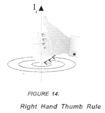
Statement : If a current carrying conductor is imagined to be held in the right hand such that the thumb points in the direction of the current, then the curled fingers of the hand indicate the direction of magnetic field (Figure 14).
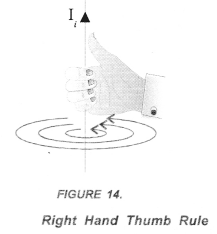
If current in a conductor flows in the upward direction, then the direction of magnetic field around the conductor is in anticlockwise direction. On the other hand, if current in a conductor flows in the downward direction, then the direction of the magnetic field around the conductor is in clockwise direction.
Question 15.
State the rule to determine the direction of a force experienced by a current-carrying straight conductor placed in a magnetic field which is perpendicular. (CBSE 2013, 2014, 2015)
Answer:
Fleming’s left hand rule
Statement : Stretch the left hand such that the thumb, first finger and the central finger are mutually perpendicular to each other. If the First finger points in the direction of the magnetic Field and the Central finger points in the direction of Current, then the thumb will point in the direction of Motion (or Force) as shown in figure 24.
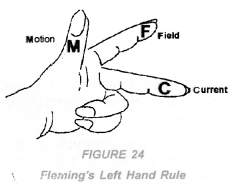
Thus, in Fleming’s left hand rule, first finger shows the direction of the magnetic field. The central finger shows the direction of electric current flowing in the conductor. Thumb shows the direction of force on the conductor or the direction of motion of the conductor
Question 16.
A compass needle shows deflection when brought near a current carrying conductor. Why ? (CBSE 2015)
Answer:
A compass needle is a small magnet. When it is brought near a current carrying’ conductor, it experiences a magnetic force due to the magnetic field around the current carrying conductor. Hence, it gets deflected due to this magnetic force.
Question 17.
Draw a sketch of the pattern of field lines due to a current flowing through a straight conductor.
[CBSE (Delhi) 2009, 2011]
Answer:
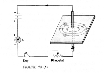
Based on magnetic field due to current passing through a circular wire or loop
Question 18.
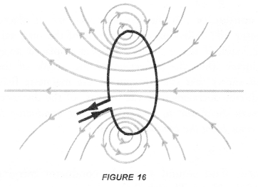
Draw the magnetic field lines through and around a single loop of wire carrying electric current.
(CBSE 2015)
Answer:
Question 19.
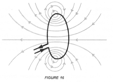
Draw the pattern of magnetic field lines of the field produced by a current carrying circular loop.
(C.B.S.E 2010, 2011, 2012)
Answer:
Based on magnetic field due to current in a solenoid
Question 20.
What is a solenoid ? (CBSE (Delhi) 2009, 2010, 2011, 2012, 2013, 2015)
Answer:
A solenoid is a long, helically wound coil of insulated copper wire.
Question 21.
Write one application of magnetic field of current carrying solenoid. (CBSE Sample Paper)
Answer:
Magnetic field of current carrying solenoid is used to make soft iron as an electromagnet.
Question 22.
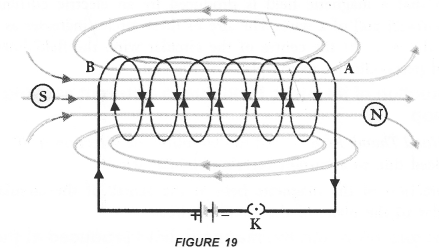
Draw the pattern of field lines of magnetic field through and around a current carrying soleniod.
(CBSE (Delhi) 2009, 2011, 2012, 2013, 2015)
Answer:
Question 23.
What does the direction of thumb indicate in the right hand thumb rule ?
Answer:
Direction of the flow of current.
Question 24.
How is an electromagnet made ?
Answer:
An electromagnet is made by placing a soft iron bar in a current carrying solenoid.
Based on force on a current carrying conductor placed in a magnetic field
Question 25.
Write an expression for the force acting on a conductor of length l carrying current (I) and placed perpendicular to the magnetic field (B).
Answer:
F = BIl
Question 26.
State the rule to determine the direction of a force experienced by a current-carrying straight conductor placed in a magnetic field which is perpendicular. (CBSE 2013, 2014, 2015)
Answer:
Fleming’s left hand rule
Statement : Stretch the left hand such that the thumb, first finger and the central finger are mutually perpendicular to each other. If the First finger points in the direction of the magnetic Field and the Central finger points in the direction of Current, then the thumb will point in the direction of Motion (or Force) as shown in figure 24.
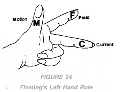
Thus, in Fleming’s left hand rule, first finger shows the direction of the magnetic field. The central finger shows the direction of electric current flowing in the conductor. Thumb shows the direction of force on the conductor or the direction of motion of the conductor.
Based on electric motor
Question 27.
What is electric motor ? (CBSE 2012)
Answer:
A device which converts electrical energy into mechanical energy.
Question 28.
What is the principle of electric motor ? (CBSE 2012)
Answer:
A current carrying conductor placed perpendicular to the magnetic field experiences a force.
Based on Electromagnetic Induction.
Question 29.
Define electromagnetic induction. (CBSE 2011, 2012, 2015)
Answer:
The phenomenon of producing induced current in a closed coil due to the changing magnetic field is called electromagnetic induction.
Question 30.
State the rule of determine the direction of current induced in a coil due to its rotation in a magnetic field.
(CBSE 2015)
Answer:
Fleming stated a rule to determine the direction of induced current in a conductor. This rule is known as Fleming’s Right hand rule.
Fleming’s Right hand Rule: “Stretch the right hand such that the first finger, the central finger and the thumb are mutually perpendicular to each other. If the First finger points along the direction of the field (magnetic field) and the Thumb points along the direction of Motion of the conductor, then the direction of induced. Current is given by the direction of the Central finger (Figure 30).
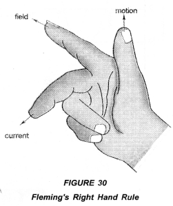
Thus, in right hand rule, first finger shows the direction of the magnetic field. The central finger shows the direction of induced current in the conductor. The thumb shows the direction of motion of the conductor in the magnetic field.
Note : Fleming’s Right hand rule is also known as Dynamo Rule.
Question 31.
How is induced current in a secondary coil related to current in a primary coil ? [CBSE (All India) 2009)]
Answer:
When current in a primary coil changes, induced current in the secondary coil is set up.
Question 32.
Name any one method to induce current in a coil. (CBSE 2015)
Answer:
Electromagnetic induction.
Based on Direct current and Alternating current
Question 33.
What is frequency of AC in India ? (CBSE 2010, 2011, 2013)
Or
State the frequency of power supply generated in India. (CBSE 2012)
Answer:
50 Hz
Question 34.
What is the frequency of direct current (D.C) ? (CBSE 2013)
Answer:
Zero.
Question 35.
What is the meaning of the term “frequency” of an alternating current ? What is its value in India ?
(CBSE Sample Paper, CBSE 2014, 2015)
Answer:
Frequency of an alternating current means how many cycles it makes in one second. In India, frequency of AC is 50Hz or cycle/second.
Question 36.
Why is an alternating current considered to be advantageous over direct current for long range transmission of electric energy 1 (CBSE Sample Paper, 2012, 2014)
Or
State one advantage of A.C. over D.C. (CBSE 2011, 2014, 2015)
Answer:
AC can be transmitted to long distant places without much loss of electric energy with the help of a transformer.
Question 37.
How is the type of current that we receive in domestic circuit different from the one that runs a clock ?
(CBSE 2015)
Answer:
The current received in domestic circuit is alternating current and the one that runs a clock is direct current. Alternating current varies in magnitude and changes its direction periodically. However, magnitude of direct current may or may not change with passage of time but its direction remains the same.
Based on electric generator
Question 38.
What is electric generator ?
Answer:
A device used to convert mechanical energy into electrical energy.
Based on Domestic Electric Circuits
Question 39.
Out of three wires live, neutral and earth, which one goes through ON/OFF switch ? (CBSE 2013, 15)
Answer:
Live wire.
Question 40.
In a domestic electric circuit, mention the potential difference between live wire and neutral wire and frequency of A.C. (CBSE 2013)
Answer:
220 V and 50 Hz.
Question 41.
Mention the colour convention for live, neutral and earth wires. (CBSE 2015)
Answer:
Live wire is covered with an insulation of red or brown colour. Neutral wire is covered with an insulation of black colour and earth wire is covered with an insulation of green or yellow colour.
Question 42.
What do you understand by the current rating of an electric fuse ? (CBSE 2012)
Answer:
The maximum amount of current that can be passed through the fuse wire without melting it.
Question 43.
Name the material generally used to make electric fuse. (CBSE 2006, 2012, 2013, 2014, 2015)
Answer:
Copper or alloy of lead and tin.
Question 44.
An alternating current has frequency of 50 Hz. How many times does it change its direction in one secotid ? [CBSE (Delhi) 2004 (S), 2012, 2013]
Or
How many times does AC used in India change direction in one second ? (CBSE Sample Paper)
Answer:
Since frequency is 50 Hz, so a.c. completes 50 cycles in 1 second. Therefore, it reverses its direction 100 times in one second.
Question 45.
List two characteristics of the material to be used in fuse wire. (CBSE 2014, 2015)
Answer:
- Melting point of the material used to make fuse wire should be low.
- Resistance should be low.
Question 46.
State the function of a ‘fuse’ in a circuit. How is it connected in the domestic circuit ? (CBSE 2013, 2014)
Answer:
Fuse is a safety device which prevents the damage of an electric, appliance connected in a circuit. It is connected in series in the domestic circuit.
Question 47.
Name the electric device that converts mechanical energy into electric energy.(CBSE Sample Paper 2017-18)
Answer:
Electric generator.
Question 48.
What is the function of earth wire in electrical instruments ? (CBSE Sample Paper 2017-18)
Answer:
Earth wire in electrical instruments save us from electric shocks.
Question 49.
Explain what is short circuiting of an electric supply. (CBSE Sample Paper 2017-18)
Answer:
When live wire and neutral wire of an electric circuit comes in direct contact accidently, then short circuiting takes place.
Question 50.
What is the usual current rating of the fuse wire in the line to feed
(a) lights and fans ?
(b) Appliances of 2 kW or more power ? (CBSE Sample Paper 2017-18)
Answer:
(a) 5 A
(b) 15 A.
Short Answer Questions (2 & 3 Marks)
Based on magnet and magnetic field
Question 1.
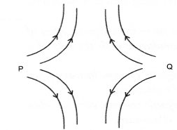
In the figure below, identify the poles marked P and Q as North Pole or South pole. Give reason for your answer. (CBSE 2010)
Answer:
Both P and Q are North poles. Magnetic field lines emerge from North pole.
Based on magnetic field due to current through a straight conductor
Question 2.
State the factors on which the strength of magnetic field at a point due to a current carrying conductor depends. State the rule which gives the direction of magnetic field. (CBSE 2010, 2013)
Answer:
The strength of magnetic field at a point due to current carrying conductor depends on
- strength of electric current flowing in the conductor.
- the distance of the point from the conductor.
Right hand thumb rule: If a current carrying conductor is imagined to be held in the right hand such that the thumb points in the direction of the current, then the curled fingers of the hand indicate the direction of magnetic field (Figure 14).
Question 3.
Describe an activity to show that magnetic field is generated around straight current carrying wire.
[CBSE (All India) 2008, 2010, 2011, 2013, 2015]
Or
With the help of a labelled circuit diagram describe an activity to illustrate the pattery of the magnetic field lines around a straight current carrying long conducting wire. (CBSE Sample Paper 2017-2018)
Answer:
Describe an activity to plot the magnetic field around a straight conductor carrying current.
- Take the thick piece of wire consisting of ten turns of insulated copper wire and a card board.
- Pass this thick wire through a hole in the card board placed horizontally as shown in Fig 13.a
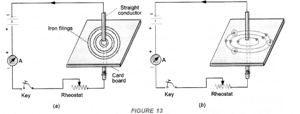
- Now pass electric current (about 4 A) through the wire by pressing the key and sprinkle some iron filings on the card board around the wire.
- Tap the card board gently.
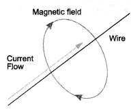
Observation : We find that the iron filings are arranged in concentric circles around the wire as shown in figure 13(a). If magnetic compass is placed near the current carrying wire and at different positions, we get concentric circles around the wire as shown in figure 13(b). These concentric circles around the wire carrying current represent the magnetic field around the wire.
Question 4.
A horizontal power line carries current in east to west direction.What is the direction of the magnetic field due to the current in the power line at a point above and at a point below the power line ?
(CBSE 2013, 2015)
Answer:
According to right-hand thumb rule :
- the direction of magnetic field at a point above the power line is from south to north,
- the direction of magnetic field at a point below the power line is from north to south.

Question 5.
A magnetic compass is placed near a current carrying wire. What will you observe
- When current in the wire is increased,
- When the magnetic compass is displaced away from the wire ?
Or
A magnetic compass shows a deflection near a current carrying wire. How will the deflection of the compass get affected if current in the wire is increased ? Support your answer with reason.
(CBSE Sample Paper 2012, 2013)
Answer:
- We observe that the deflection of the needle of the magnetic compass increases. This is because the magnetic field strength due to a current carrying wire increases, when current in the wire is increased.
- We observe that the deflection of the needle of the magnetic compass decreases. This is because the magnetic field strength due to a current carrying wire decreases with the increase of the distance from the wire.
Question 6.
Draw a diagram to show how a magnetic needle deflects when it is placed above or below a straight conductor carrying current de¬pending on the direction of the current in the conductor.
(CBSE 2010)
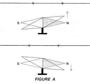
Answer:
Direction of deflection of magnetic needle due to the current pass¬ing through a conductor can be found using Ampere’s swimming rule as shown in figure A.
Question 7.
A student performs an experiment to study the magnetic effect of current around a current carrying conductor with the help of a magnetic compass. He reports that :
- The degree of deflection of the magnetic compass increases when the compass is moved away from the conductor.
- The degree of deflection of the magnetic compass increases when the current through the conductor is increased
Which of the above observations of the student appears to be wrong and why ? (CBSE 2010, 2011)
Answer:
Observation
- is incorrect. Degree of deflection of magnetic compass depends on the strength of the magnetic field produced by the current carrying conductor. Magnetic field increases with the increase in the current through the conductor and hence degree of deflection of the magnetic compass increases.
- Magnetic field decreases with the increase in the distance from the conductor and hence degree of deflection of the magnetic compass decreases when the compass is moved away from the conductor.
Question 8.
With the help of a diagram describe an activity to show that an electric current can affect a magnet.
(CBSE 2014)
Answer:
When a straight conductor carries electric current (dc), a magnetic field is set up around the conductor. This magnetic field causes the deflection in the needle of the magnetic compass.
Describe an activity to plot the magnetic field around a straight conductor carrying current.
- Take the thick piece of wire consisting of ten turns of insulated copper wire and a card board.
- Pass this thick wire through a hole in the card board placed horizontally as shown in Fig 13.a.
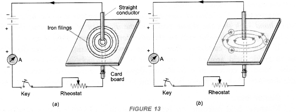
- Now pass electric current (about 4 A) through the wire by pressing the key and sprinkle some iron filings on the card board around the wire.
- Tap the card board gently.
Observation : We find that the iron filings are arranged in concentric circles around the wire as shown in figure 13(a). If magnetic compass is placed near the current carrying wire and at different positions, we get concentric circles around the wire as shown in figure 13(b). These concentric circles around the wire carrying current represent the magnetic field around the wire.
Based on force on a current carrying conductor placed in a magnetic field
Question 9.
Why does a current carrying conductor kept in a magnetic field experience force ? What is the direction of force acting on the conductor ? (CBSE 2010, 2011, 2015)
Answer:
A current carrying conductor contains moving negatively charged particles (i.e., electrons). Each electron experiences a force (= Bev). The total force experienced by electrons is equal to the force experienced by the conductor. This force acts perpendicular to both the magnetic field and the direction of current in the conductor. The direction of the force acting on the conductor is determined by Fleming’s left hand rule.
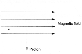
A proton enters a magnetic field at right angles to it as shown in figure.
Question 10.
What is the direction of the force acting on the proton ?
Answer:
According to Fleming’s left hand rule, the force acting on a current
carrying conductor placed at right angles to a magnetic field is perpendicular to the directions of current {i.e. flow of positive charges) and the magnetic field.
The arrow showing the direction of proton represents the direction of current in a conductor, therefore, the force acting on the conductor is perpendicular to the plane of the paper and in upward direction.
Question 11.
State the rule to determine the direction of force experienced by a current carrying conductor in a magnetic field. How will this force get affected on :
- Doubling the magnitude of current ?
- Reversing the direction of current flow ? (CBSE 2010)
Answer:
Fleming’s left hand rule:
Statement : Stretch the left hand such that the thumb, first finger and the central finger are mutually perpendicular to each other. If the First finger points in the direction of the magnetic Field and the Central finger points in the direction of Current, then the thumb will point in the direction of Motion (or Force) as shown in figure 24.
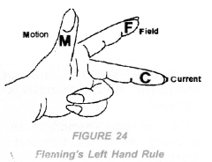
Thus, in Fleming’s left hand rule, first finger shows the direction of the magnetic field. The central finger shows the direction of electric current flowing in the conductor. Thumb shows the direction of force on the conductor or the direction of motion of the conductor
Force, F = B I l.
- When magnitude of current is doubled, the magnitude of the force is also doubled.
- The direction of the force is reversed, when the direction of the current flow is reversed.
Question 12.
A student while studying the force experienced by a current carrying conductor in a magnetic field records the following observations :
- The force experienced by the conductor increases as the current is increased.
- The force experienced by the conductor decreases as the strength of the magnetic field is increased.
Which of the two observations is correct and why ? (CBSE 2010, 2011)
Answer:
Force experienced by a current carrying conductor in a magnetic field is given by F = B I l, where B is magnetic field, I is current and l is the length of the conductor.
Observation
- is correct because F increases with increase in I. However, observation
- is incorrect because F increases with increase in B.
Question 13.
Describe with the help of a labelled diagram an activity to demonstrate the force acting on a current carrying conductor due to magnetic field. (CBSE 2014, 2015)
Answer:
Describe an activity to show that a current carrying conductor placed perpendicular to the magnetic field experiences a force.
- Fix a horse shoe magnet on the top of the table.
- Place a long and thin strip of aluminium on two wooden supports such that it passes between the North and South poles of the magnet.
- Connect a battery across the ends of the aluminium strip through a key (K) as shown in Figure 23(a).

- Now close the key so that current (I) flows through the strip. [Figure 23 (b)].
Observation: When current flows through the aluminium strip, it moves upward. If the direction of current is reversed, the aluminium strip moves downward.
Conclusion: A current carrying conductor (aluminium strip) placed in a magnetic field experiences a force in a direction perpendicular to the direction of the magnetic field. Due to this force, the current carrying conductor is displaced from its rest position.
Question 14.
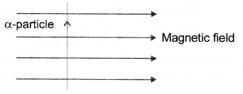
An α-particle enters a uniform magnetic field at right angles to it as shown in figure. Stating the relevant principle, explain in which direction will this α.-particle move ? (CBSE 2014)
Answer:
According to Fleming’s left hand rule, the force acting on a current carrying conductor placed perpendicular to a magnetic field is perpendicular to the direction of current (i. e., flow of positive charges) and the magnetic field. Here, direction of α-particle (i.e., positive charge) is the direction of current. Hence, according to Fleming’s left hand rule, the direction of force acting on α-particle is perpendicular to both the direction of motion of α-particle and the direction of magnetic field. Hence, α-particle will move perpendicular to the plane of the paper and in downward direction.
Question 15.
State whether an alpha particle will experience any force in a magnetic field if (alpha particles are positively charged particles)
- it is placed in the field at rest.
- it moves in the magnetic field parallel to field lines.
- it moves in the magnetic field perpendicular to field lines.
Justify your answer in each case. (CBSE 2015)
Answer:
Force acting a particle having charge q moving with velocity u in a magnetic field B is given by
F = qv B sin θ …………..(i)
where θ is the angle between velocity V and magnetic field B.
- When alpha particle is at rest i.e. V = 0, then
F = 0 (No force) - When alpha particle moves parallel to the magnetic field, θ = 0°, then
F = qvB sin 0° = 0 (No force) - When alpha particle moves perpendicular to magnetic field, θ = 90°, then
F = qvB sin 90° = qvB (maximum force) on magnetic field due to current passing through a circular wire or loop
Question 16.
How does the strength of the magnetic field at the centre of a circular coil of a wire depends on
(a) radius of the coil
(b) number of turns of the wire of the coil ? (CBSE 2010, 2011, 2012, 2015)
Answer:
The strength of magnetic field at the centre of the circular coil is
(a) inversely proportional to the radius of the coil and
(b) directly proportional to the number of turns of the wire of coil.
Question 17.
The magnetic field produced by a current carrying circular coil having n turns is equal to n times the magnetic field produced by a current carrying circular coil having a single turn. Explain, why ? (NCERT Question Bank)
Answer:
As the direction of the current flowing in each turn of the coil is same, so the direction of the magnetic field produced by each turn is also the same. The magnetic field produced by each turn will therefore get added up to give the magnetic field produced by a coil of n turns. Hence, magnetic field produced by a coil of n turns = n times the magnetic field produced by a coil having a single turn.
Question 18.
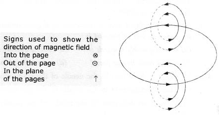
Current is flowing clockwise in a circular coil lying in the plane of a table. Using Right Hand Thumb rule, state the direction of the magnetic field inside and outside the coil.
Or
Consider a circular loop of wire lying in the plane of a table. Let the current pass through the loop clockwise. Apply the right hand rule to find the direction of the magnetic field inside and outside the loop. [CBSE (Delhi) 2009]
Answer:
Magnetic field inside the coil is perpendicular to the plane of the table and in the downward
direction. However, outside the coil, the magnetic field is perpendicular to the plane of the table and in the upward direction.
Question 19.
How will the magnetic field be produced in a current carrying circular coil change if we
- increase the value of current
- increase the distance from the coil
- increase the number of turns of the coil. (CBSE 2010, 2011)
Answer:
Magnetic field will
- increase with the increase in the value of current
- decrease with the increase in the distance from the coil and
- increase with the increase in the number of turns of the coil.
Question 20.
Describe an activity to show that magnetic field is produced by an electric current flowing through a circular coil of a wire. [CBSE (Foreign) 2008, 2010]
Answer:
Describe an activity to plot the magnetic field around a current carrying circular coil of a wire.
- Take a thick copper wire in the form of a circular loop. Pass this circular wire through a cardboard supported over a table in the horizontal position (Figure 17).
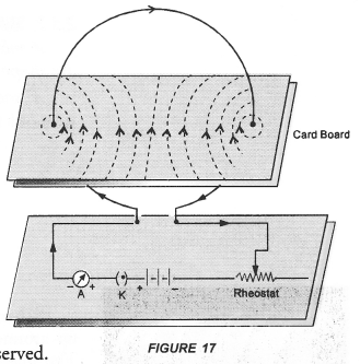
- Now connect the ends of this wire with a battery through a key (K), rheostat and ammeter (A).
- Allow the current to flow through the circular wire by closing the key K.
- Now plot magnetic field lines around the wire with the help of a magnetic compass needle.
Observations: Magnetic field lines as shown by dotted circles are observed. This shows that a magnetic field is produced by an electric current flowing through a circular coil of a wire. The size of these circles increases as we move away from the wire. At the centre of the circular wire, the field lines become straight and perpendicular to the plane of the coil.
Based on magnetic field due to current in a solenoid
Question 21.
On what factors does the magnetic field produced by a current carrying solenoid depend?
(CBSE 2011, 2012, 2013)
Answer:
- the strength of the current flowing through the solenoid.
- the number of turns of the wire of the solenoid.
- the nature of the material inside the solenoid.
Based on Electromagnetic Induction
Question 22.
Name the scientist who discovered that a moving magnet can be used to generate electric current. With which name is this phenomenon known ? (CBSE 2011, 2015)
Answer:
Michael Faraday. Electromagnetic Induction.
Question 23.
What is an electromagnet ? Mention any two uses of an electromagnet. (CBSE 2013)
Answer:
A soft iron placed inside a current carrying solenoid acts as an electromagnet. Electromagnet is used in electric bells, telephone receivers, microphones, to lift iron pieces etc.
Question 24.
Give three differences between an electromagnet and a permanent magnet. (CBSE 2015)
Answer:
|
Electromagnet |
Permanent Magnet |
| 1. It behaves as a magnet as long as electric current passes through the solenoid surrounding it. It is demagnetised when electric current stops passing through the solenoid. Thus, electromagnet is a temporary magnet. | 1. It cannot be demagnetised easily. It can be demagnetised either by heating it or throwing it times and again on the floor from certain height. |
| 2. Electromanget gives a strong mangetic field and the strength of the magnetic field produced by the electromagnet can be increased or decreased by increasing or decreasing electric current through the solenoid. | 2. Magnetic field of a permanent magnet is weak. The strength of magnetic field of the permanent magnet cannot be changed. |
| 3. The polarity (i.e. North and South poles) of an electromagnet can be reversed by reversing the direction of electric current through the solenoid. | 3. The polarity of a permanent magnet cannot be reversed. |
Question 25.
What are permanent magnet and electromagnet ? Give two uses of each.
Answer:
Permanent magnet has fixed north and south pole. The strength of the magnetic field of a permanent magnet cannot be changed.
When a soft iron rod is placed inside a current carrying solenoid, it becomes an electromagnet. The strength of the magnetic field of an electromagnet can be increased or decreased by increasing or decreasing the current flowing in the solenoid. The polarity of electromagnet can be changed by changing the direction of current through the solenoid.
Uses of permanent magnet : Permanent magnets are used in loudspeakers and simple electric motors.
Uses of electromagnet : Electromagnets are used in electric bells, electric horns, television etc.
Question 26.
Explain the meaning of the word “electromagnetic” and “induction” in the term electromagnetic induction.
(CBSE Sample Paper, CBSE 2014)
Answer:
“Electromagnetic” means production of induced current in a closed coil due to the change in magnetic field. “Induction” means the induced current is produced without the actual contact of the closed coil and the moving magnet.
Question 27.
A coil of insulated wire is connected to a galvanometer. What would be seen if a bar magnet with its south pole towards one face of the coil is
(a) moved quickly towards it ?
(b) moved quickly away from it ?
(c) placed near its one face ?
(d) name the phenomena involved. (CBSE 2010)
Answer:
(a) There is deflection in the needle of the galvanometer.
(b) There is deflection in the needle of the galvanometer but in opposite direction.
(c) There is no deflection in the needle of the galvanometer.
(d) Electromagnetic induction.
Question 28.
A coil made of insulated copper wire is connected to a galvanometer. What will happen to the deflection of the galvanometer if this coil is moved towards a stationary bar magnet and then moved away from it ? Give reason for your answer and name the phenomenon involved. (CBSE 2010, 2011)
Answer:
When coil is moved towards a stationary bar magnet, magnetic field linked with coil increases. Hence, induced current is produced in the coil. Due to this current, needle of galvanometer deflects. When coil is moved away from the coil, magnetic field linked with the coil decreases, Hence, induced current is again produced in the coil but in opposite direction. Thus, needle of galvanometer deflects but in opposite direction.
Phenomenon : Electromagnetic induction.
Based on Direct current and Alternating current
Question 29.
Current-time graphs from two different sources are shown in the following diagrams.
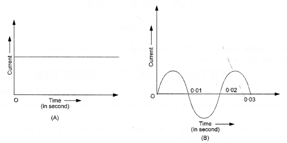
Now answer the following questions.
- Name the type of current shown by graph A and graph B.
- Name any one source of the current shown by graph A and graph B.
- What is the frequency of current in case B ?
- Write two difference between the current shown by graphs A and B. (CBSE 2010)
Or
Write one difference between A.C. and DC. (CBSE 2012, 2013, 2015)
Answer:
- Graph A represents direct current (DC). Graph B represents alternating current (AC).
- A dry cell is the source of current shown by graph’A. An AC generator is the source of current shown by the graph B.
- From graph B, time period, T = 0.02 s. Therefore, frequency of current,

-
Direct current Alternating current
1. The magnitude of direct current is constant and flows in one direction only. 2. Direct current cannot be used for large scale supply of electricity for household purpose.
3. The frequency of direct current is zero.
1. The magnitude of AC changes with time and direction of alternating current reverses periodically. 2. Alternating current is used to run electrical appliances like electric bulb, electric heater, electric iron, refrigerator etc.
3. Frequency of alternating current in India is 50 Hz.
Question 30.
What is the basic difference between AC generator and DC generator ?
Answer:
- In AC generator, slip-ring type commutator is used and in DC generator split-ring type commutator is used.
- AC generator converts mechanical energy into electrical energy in the form of alternating current. DC generator converts mechanical energy into electrical energy in the form of direct current.
Based on Domestic Electric circuit
Question 31.
List two safety measures commonly used in electric circuits. Explain the main function of each.
(CBSE 2015)
Answer:
Alternating current flowing through a wife is dangerous if the wire is touched bare footed. Moreover, when current flowing through the wire exceeds a certain limit, it can burn the electric circuit. So, we have to take safety measures while using electricity.
These safety measures are given below :
-
-
- Electric Fuse. An electric fuse is a safety device used to save the electrical appliances like electric bulbs, electric, tubes, T.V. etc. from burning when large current flows in the circuit. Electric fuse is a wire made of copper or aluminium or tin-lead alloy. The melting point of the material of which the electric fuse wire is made should be low. Electric fuse is connected in series with an electric device like bulb, T.V., refrigerator etc.
Suppose a fuse is not connected in the path of a live wire of the circuit, in such case, the circuit may be over heated if the current in the circuit exceeds the safe limit. There is a chance of short circuiting of the circuit which causes the fire. So to avoid short circuiting of the circuit, a fuse must be put in the path of the circuit.
Fuse wares are usually rated as 5 A or 15 A. A circuit in which bulb or a tube is to be connected, the fuse is rated as 5 A. It means, this circuit can 4 draw maximum 5 A current. If current in this circuit becomes greater than 5 A, the fuse wire melts and the circuit is switched off automatically. Hence the circuit can be saved from burning.
Similarly, a circuit in which a heating appliance like an electric heater or a geyser is to be connected, the fuse rated as 15 A is used. Commonly used, electric fuses are shown in Figure 36.
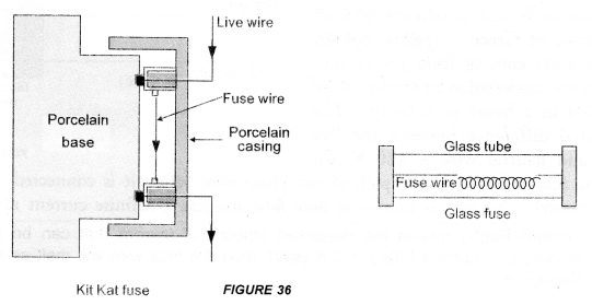
- Electric Fuse. An electric fuse is a safety device used to save the electrical appliances like electric bulbs, electric, tubes, T.V. etc. from burning when large current flows in the circuit. Electric fuse is a wire made of copper or aluminium or tin-lead alloy. The melting point of the material of which the electric fuse wire is made should be low. Electric fuse is connected in series with an electric device like bulb, T.V., refrigerator etc.
-
- The insulation on the wire should be of high strength so that it may not melt easily when wires are heated due to large current flowing through them.
- Wires carrying electricity should not be touched bare footed. The live wire is at higher potential and the earth is at zero potential. If we touch the live wire bare footed, a large current will pass through our body. So we will receive a severe shock. This shock affects our nervous system and may cause even death. Therefore, while using electricity, we must wear gloves made of insulated material and shoes of rubber sole so that current may not flow through our body.
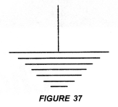
- Electric appliances like heater, toaster, refrigerator etc. are frequently touched by us with bare hands. If per chance, the insulation on live wire melts, then the live wire may touch the metallic case of the appliance. In that case, current passes though the metal casing of the appliance. If we touch this casing with bare hands, we will receive a severe shock. To avoid such an accident, metal casings of all electric appliances must be earthed. One end of copper wire is connected with metal casing of the electric appliance. The other end of the copper wire is connected to the copper plate which is buried deep inside the earth. This system of connecting the metal casing of an electric appliance with a copper plate buried deep inside the earth is known as earthing. Earthing is represented by a symbol shown in figure 37.
Question 32.
An electric fuse of rating 3 A is connected in a circuit in which an electric iron of power 1 kW is connected which operates at 220V. What would happen ? Explain. (CBSE 2012)
Answer:

This current is greater than the rating of the fuse (i.e. 3A). Hence, the fuse will melt and the circuit breaks. Therefore, electric iron will not work.
Long Answer Questions
Question 1.
Explain, the construction and working of an electric motor using a well labelled diagram.
Answer:
Electric motor converts electrical energy into mechanical energy.
Principle: Electric Motor is based on the fact that a current carrying conductor placed perpendicular to the magnetic field experiences a force.
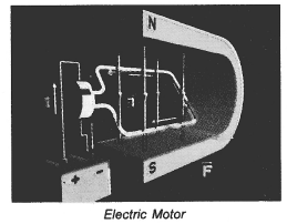
- Armature coil: It consists of a single loop of an insulated copper wife in the form of a rectangle. Rectangle ABCD shown in figure 25 is an armature coil.
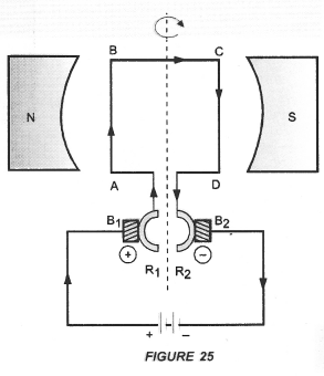
- Strong field magnet: Armature coil is placed between two pole pieces (N and S poles) of a strong magnet. This magnet provides a strong magnetic field.
- Split-ring type Commutator. It consists of two halves (R1 and R2) of a metallic ring. The two ends of the armature coil are connected to these two halves of the ring. Commutator reverses the direction of current in the armature coil.
- Two carbon brushes B1 and B2 press against the commutator. These brushes act as the contacts between the commutator and the terminals of the battery.
- A battery is connected across the carbon brushes. This battery supplies the current to the armature coil.
Question 2.
Describe the construction and working of A.C. generator with the help of a labelled diagram. How can you convert AC generator to DC generator ?
Answer:
An electric device used to convert mechanical energy (kinetic energy) into electrical energy (electricity) is called an electric generator.
Principle: Electric generator works on the principle of electromagnetic induction. When the coil of electric generator rotates in a magnetic field, induced current flows in the circuit connected with the coil.
types of electric generator
- AC generator
- DC generator
AC generator: AC generator converts mechanical energy into electrical energy in the form of alternating current or AC.
DC generator: DC generator converts mechanical energy into electrical energy in the form of direct current or DC. AC Generator Construction : The main components of AC generator are (Figure 33) :
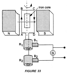
- Armature : Armature coil (ABCD) consists of large number of turns of insulated copper wire wound over a soft iron core.
- Strong field magnet : A strong permanent magnet or an electromagnet whose poles (N and S) are cylindrical in shape is a field magnet. The armature coil rotates between the pole pieces of the field magnet. The uniform magnetic field provided by the field magnet is perpendicular to the axis of rotation of the coil.
- Slip Rings : The two ends of the armature coil are connected to two brass slip rings R1 and R2. These rings rotate along with the armature coil. Rings R1 and R2 are at different heights.
- Brushes : Two carbon brushes (B1 and B2), are pressed against the slip rings. The brushes are fixed while slip rings rotate along with the” armature. These brushes are connected to the external circuit across which the output is obtained.
Working : When the armature coil ABCD rotates in the magnetic field provided by the strong field magnet, it cuts the magnetic field lines. Thus, the changing magnetic field produces induced current in the coil. The direction of the induced current in the coil is determined by the Fleming’s right hand rule.
The current flows out through the brush B1 in one direction in the first half of the revolution and through the brush B2 in the next half revolution in the reverse direction. This process is repeated. Therefore, induced current produced is of alternating nature. Such a current is called alternating current.
DC generator or Dynamo Construction:
- Armature coil. It consists of large number of turns of insulated copper wire wound on iron core in the form of a rectangle coil. Rectangle coil ABCD shown in figure 34 is an armature coil.
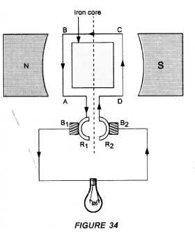
- Strong field magnet. Armature coil is placed between two pole pieces (N and S poles) of a strong magnet. This magnet provides a strong magnetic field.
- Split-ring Type Commutator. It consists of two halves (R1 and R2) of a metallic ring. The two ends of the armature coil are connected to these two halves of the ring.
- Two carbon brushes B1 and B2 press against the commutator.
- The output is shown by the glowing bulb connected across the carbon brushes.
Working of d.c. generator: When the coil of d.c. generator rotates in the magnetic field, induced potential difference is produced in the coil. This induced potential difference gives rise to the flow of current through the bulb and hence the bulb glows.
In d.c. generator, the flow of current in the circuit is in the same direction as long as the coil rotates in the magnetic field. This is because one brush is always in contact with the arm of the armature moving up and the other brush is in contact with the arm of the armature moving downward in the magnetic field.
Note: AC generator can be converted into DC generator by replacing slip rings used in AC generator by a split ring type commutator.
Question 3.
What is an electromagnet ? What decides its polarity ? How it differs from a permanent magnet ? List the three factors and explain how strength of an electromagnet depends on these. (CBSE 2013)
Answer:
When a soft iron bar is placed inside a solenoid carrying current, it becomes a magnet as long as current flows through the solenoid. Such a magnet is known as electromagnet.
In fact, the magnetic field inside the solenoid magnetises the soft iron bar placed in it, which acts as an electromagnet. (Figure 22).
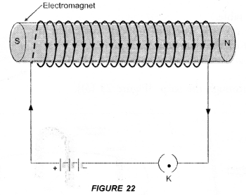
Strength of an electromagnet can be increased by
- increasing the current through solenoid and
- increasing the number of turns of the solenoid. The polarity of electromagnet is decided by the direction of current flowing in the solenoid.
Uses of electromagnets
- They are used to lift heavy iron pieces. They are fitted on cranes heavy objects of scrap iron.
- They are used in many devices like electric bell, electric horn, telephone receiver, electric relay, microphones, radio set, television, loudspeakers etc.
|
Electromagnet |
Permanent Magnet |
| 1. It behaves as a magnet as long as electric current passes through the solenoid surrounding it. It is demagnetized when electric current stops passing through the solenoid. Thus, electromagnet is a temporary magnet. | 1. It cannot be demagnetised easily. It can be demagnetised either by heating it or throwing it times and again on the floor from certain height. |
| 2. Electromanget gives a strong mangetic field and the strength of the magnetic field produced by the electromagnet can be increased or decreased by increasing or decreasing electric current through the solenoid. | 2. Magnetic field of a permanent magnet is weak. The strength of magnetic field of the permanent magnet cannot be changed. |
| 3. The polarity (i.e. North and South poles) of an electromagnet can be reversed by reversing the direction of electric current through the solenoid. | 3. The polarity of a permanent magnet cannot be reversed. |
Question 4.
Describe an activity to show how a moving magnet may be used to generate an electric current. State the rule to find the direction of electric current generated in a coil in this manner.
(CBSE 2015)
Answer:
When a bar magnet moves towards or away from the closed coil, galvanometer shows a deflection. The deflection in the galvanometer indicates that current is flowing through the coil. This electric current is called induced electric current.
It was Michael Faraday, who performed a simple experiment to show that an electric current can be produced in a closed circuit without the use of an electro-chemical cell or battery but by moving a bar magnet towards or away from the closed circuit.
Explanation :
- When a magnet is moved towards the coil, more and more magnetic field lines pass through the coil as shown in figure 28(b).

Thus, magnetic field around the coil increases. The increase in magnetic field induces potential difference (or voltage) across the ends of the coil. As the coil connected to the galvanometer forms a closed circuit, so induced potential difference makes the current to flow through the circuit. The presence of this current in the circuit is shown by the deflection of the galvanometer. - When a magnet is moved away from the coil, the magnetic field around the coil decreases. The decrease in magnetic field induces potential difference across the ends of the coil. This induced potential difference (or voltage) produces current in the circuit. The presence of the current in the circuit is shown by the deflection of the galvanometer. The current in the circuit is known as induced current.
- When the magnet is stationary, the magnetic field around the coil is constant. Therefore, no potential difference is set up across the coil. Hence, no current flows through the circuit.
Direction of Induced Current in a Conductor (Fleming’s Right Hand Rule):
Fleming stated a rule to determine the direction of induced current in a conductor. This rule is known as Fleming’s Right hand rule.
Fleming’s Right hand Rule: “Stretch the right hand such that the first finger, the central finger and the thumb are mutually perpendicular to each other. If the First finger points along the direction of the field (magnetic field) and the Thumb points along the direction of Motion of the conductor, then the direction of induced. Current is given by the direction of the Central finger (Figure 30).
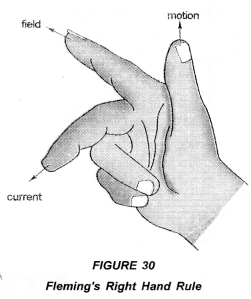
Thus, in right hand rule, first finger shows the direction of the magnetic field. The central finger shows the direction of induced current in the conductor. The thumb shows the direction of motion of the conductor in the magnetic field.
Note : Fleming’s Right hand rule is also known as Dynamo Rule.
Hope given Previous Year Question Papers for CBSE Class 10 Science Chapter 13 Magnetic Effects of Electric Current are helpful to complete your science homework.
If you have any doubts, please comment below. Learn Insta try to provide online science tutoring for you.