CBSE Sample Papers for Class 12 Physics Paper 5 are part of CBSE Sample Papers for Class 12 Physics. Here we have given CBSE Sample Papers for Class 12 Physics Paper 5.
CBSE Sample Papers for Class 12 Physics Paper 5
| Board | CBSE |
| Class | XII |
| Subject | Physics |
| Sample Paper Set | Paper 5 |
| Category | CBSE Sample Papers |
- All questions are compulsory. There are 26 questions in all.
- This question paper has five sections: Section A, Section B, Section C, Section D and Section E.
- Section A contains five questions of 1 mark each. Section B contains five questions of 2 marks each. Section C contains twelve questions of 3 marks each. Section D contains one value based question of 4 marks and Section E contains three questions of 5 marks each.
- There is no overall choice. However, an internal choice has been provided in 1 question of 2 marks, 1 question of 3 marks and all the 3 questions of 5 marks weightage. You have to attempt only 1 of the choices in such questions.
- You may use the following values of physical constants wherever necessary :
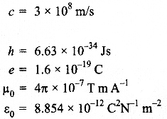
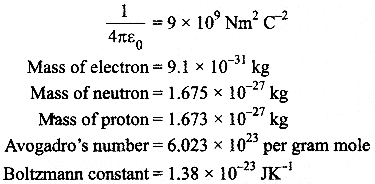
Questions
SECTION : A
Question 1.
The horizontal component of the earth’s magnetic field at a place is B and angle of dip is 60°. What is the value of vertical component of earth’s magnetic field at equator?
Question 2.
A heating element is marked 210 V, 630 W. What is the value of current drawn by the element when connected to a 210 V dc source?
Question 3.
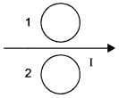
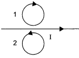
Predict the directions of induced currents in metal rings 1 and 2 lying in the same plane where current I in the wire is increasing steadily.
Question 4.
Show on a graph, the variation of resistivity with temperature for a typical semiconductor.
Question 5.
Why should electrostatic field be zero inside a conductor?
SECTION : B
Question 6.
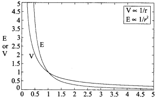
Draw a plot showing the variation of
(i) electric field (E) and
(ii) distance r due to a point charge Q.
Question 7.
Distinguish between ‘Analog and Digital signals’
OR
Mention the functions of any two of the following used in communication system :
(a) Transducer
(b) Repeater
(c) Transmitter
(d) Bandpass Filter
Question 8.
A ray of light incident on an equilateral prism (μg = \(\sqrt { 3 } \)) moves parallel to the base line of the prism inside it. Find the angle of incidence for this ray.
Question 9.
The susceptibility of a magnetic material is -2.6 x 10⁻⁵. Identify the type of magnetic material and state its two properties.
Question 10.
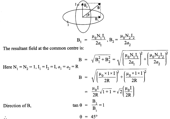
Two identical circular wires P and Q each of radius R and carrying current ‘I’ are kept in perpendicular planes such that they have a common centre. Find the magnitude and direction of the net magnetic field at the common centre of the two coils.
SECTiON : C
Question 11.
A cell of emf E and internal resistance r is connected to two external resistance R1 and R2 and a perfect ammeter. The current in the circuit is measured in four different situations :
(i) without any external resistance in the circuit
(ii) with resistance R1only
(iii) with R1 and R2 in series combination
(iv) with R1 and R2 in parallel combination.
The currents measured in the four cases are 0.42 A, 1.05 A, 1.4 A and 4.2 A, but not necessarily in the order.Identify the currents corresponding to the four cases mentioned above.
Question 12.
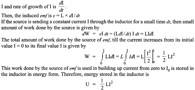
Define self-inductance of a coil. Show that magnetic energy required to build up the current I in a coil of self inductance L is given by 1/2 LI2
Question 13.
(a) Why are coherent sources necessary to produce a sustained interference pattern?
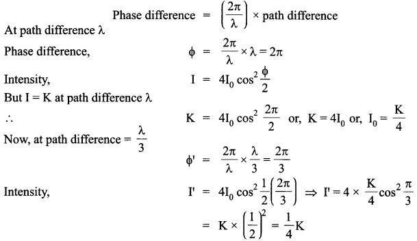
(b) In Young’s double slit experiment using monochromatic light of wavelength λ, the intensity of light at a point on the screen where path difference is λ, is K units. Find out the intensity of light at a point where path difference is λ/3.
Question 14.
When an ideal capacitor is charged by a dc battery, no current flows. However, when an ac source is used the current flows continuously. How does one explain this based on the concept of displacement current?
Question 15.
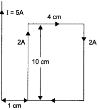
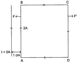
A rectangular loop of wire of size 4 cm x 10 cm carries a steady current of 2 A. A straight long wire carrying 5 A current is kept near the loop as shown. If the loop and the wire are coplanar,
find
(i) the torque acting on the loop and
(ii) the magnitude and direction of the force on the loop due to the current carrying wire.
Question 16.
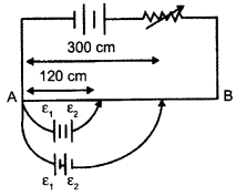
In the figure a long uniform potentiometer wire AB is having a constant potential gradient along its length. The null points for the two primary cells of emfs ε1 and ε2 connected in the manner shown are obtained at a distance of 120 cm and 300 cm from the end A.
Find
(i) ε1/ε2 and
(ii) position of null point for the cell ε1
How is the sensitivity of a potentiometer increased?
OR
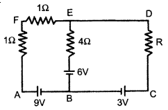
Using Kirchhoffs rules determine the value of unknown resistance R in the circuit so that no current flows through 4 Q resistance. Also find the potential between A and D.
Question 17.
Write any two factors which justify the need for modulating a signal. Draw a diagram showing an amplitude modulated wave by superimposing a modulating signal over a sinusoidal carrier wave.
Question 18.
The current in the forward bias is known to be more (~ mA) than the current in the reverse bias (~ μA). What is the reason, then, to operate the photodiode in reverse bias?
Question 19.
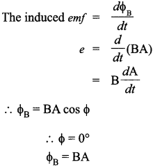
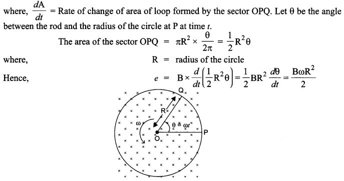
A metallic rod of length ‘L’ is rotated with angular frequency of ‘ω’ with one end hinged at the centre and the other end at the circumference of a circular metallic ring of radius L about an axis passing through the centre and perpendicular to the plane of the ring. A constant and uniform magnetic field B parallel to the axis is present everywhere. Deduce the expression for the induced em/between the centre and the metallic ring.
Question 20.
Write Einstein’s photoelectric equation. State clearly how this equation is obtained using the photon picture of electromagnetic radiation. Write the three salient features observed in photoelectric effect which can be explained using this equation.
Question 21.
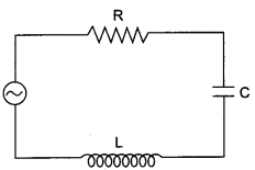
The figure shows a series LCR circuit with L = 5 H, C = 80 μF, R = 40 Ω connected to a variable frequency 240 V source, calculate
(i) the angular frequency of the source which drives the circuit at resonance,
(ii) the current at the resonating frequency,
(iii) the rmspotential drop across the inductor at resonance.
Question 22.
(i) What characteristic property of nuclear force explains the constancy of binding energy per nucleon (BE/A) in the range of mass number ‘A’ lying 30 < A < 170?
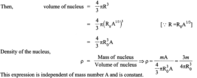
(ii) Show that the density of nucleus over a wide range of nuclei is constant independent of mass number A.
SECTION : D
Questoin 23.
Renu and her friend went to see an exhibition. There, security guard standing on the entrance gate, asked them to come through a metal detector gate. Her friend was scared of it. But Renu convinced her and explained the purpose and working of a metal detector.
(i) What values Renu possess?
(ii) What is a metal detector and how it works?
SECTION : E
Question 24.
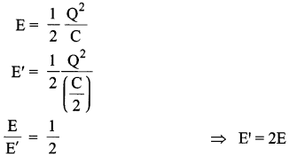
A parallel plate capacitor is charged to a potential difference V by a dc source. The capacitor is then disconnected from the source. If the distance between the plates is doubled, state with reason how the following will change;
(i) electric field between the plates
(ii) capacitance, and
(iii) energy stored in the capacitor
OR
(a) Define electric flux. Write its S.I. units.
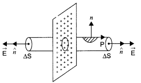
(b) Using Gauss’s law, prove that the electric field at a point due to a uniformly charged infinite plane sheet is independent of the distance from it.
(c) How is the field directed if
(i) the sheet is positively charged,
(ii) negatively charged?
Question 25.
Define magnifying power of a telescope. Write its expression. A small telescope has an objective lens of focal length 150 cm and an eye-piece of focal length 5 cm. If this telescope is used to view a 100 m high tower 3 km away, find the height of the final image when it is formed 25 cm away from the eye-piece.
OR
How is the working of a telescope different from that of a microscope? The focal lengths of the objective and eyepiece of a microscope are 1.25 cm and 5 cm respectively. Find the position of the object relative to the objective in order to obtain an angular magnification of 30 in normal adjustment.
Question 26.
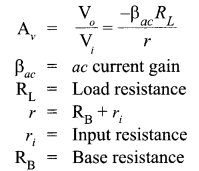
Draw a simple circuit of a CE transistor amplifier. Explain its working. Show that the voltage gain Av of the amplifier is given by

is the current again ; RL is the load resistance and r. is the input resistance of the transistor. What is the significance of the negative sign in the expression for the voltage gain?
OR
(a) Draw the circuit diagram of a full wave rectifier using p-n junction diode. Explain its working and show the output, input waveforms.
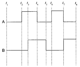
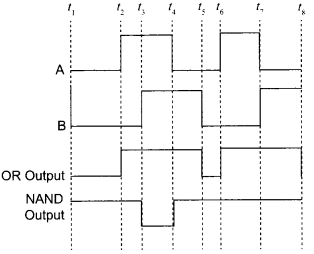
(b) Show the output waveforms (Y) for the following inputs A and B of
(i) OR gate
(ii) NAND gate.
Answers :
SECTION : A
Answer 1.
On the equator, the value of both angle of dip (5) and vertical component of earth’s magnetic field is zero. So, in this case,
Bv = 0.
Answer 2.
In dc source, P = VI
Given that P = 630 W and V = 210 V
So, I = P/V = 630/210 = 3 A.
Answer 3.
Using Lenz’s law we can predict the direction of induced current in both the rings. Induced current oppose the cause of increase of magnetic flux. So, it will be clockwise in ring 1 and anticlockwise in ring 2.
Answer 4.
The following curve shows the variation of resistivity with temperature for a typical semiconductor.
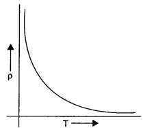
This is because for a typical semiconductor resistivity decreases rapidly with increasing temperature.
Answer 5.
Charge on conductor resides on its surface. So if we consider a Gaussian surface inside the conductor to find the electrostatic field,
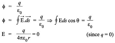
Where, q = charge enclosed in Gaussian surface. q = 0, inside the conductor, hence the electrostatic field inside the conductor is zero.
SECTION : B
Answer 6.
We know, that for a point charge Q
(i) Electric field,

(ii) Electric potential,

Thus, electric potential shows an inverse relationship while electric field shows a inverse square relationship with r. So, their corresponding plots would be
Answer 7.
Analog Signal : It is continuous signal, which varies continuously with variable may be time or distance etc.
E.g. Voice of human.
Digital Signal :
It is a type of signal which has only two values high or low. In digital signal, high means 1 and low means 0.
E.g.
Temperature of day
- Maximum 30°C ⇒ 1
- Minimum 15°C ⇒ 0
OR
(a) Transducer :
It is an electric device which converts energy from one form to another form. E.g. microphone, which converts sound energy into electric energy.
(b) Repeater :
It is an electronic device used in transmission system to regenerate the signal. It picks up a signal amplifies it and re-transmits it to receiver.
(c) Transmitter :
Transmitter is an electronic device which is used to radiate electromagnetic waves. The purpose of the transmitter is to boost up the signal to be radiated to the required power level, so that it can travel long distances. The most familiar transmitters are mobile transmitter antennas, radio and T.V broadcasting antennas etc.
(d) Bandpass filter :
It is an electronic filter, which pass the certain band (range) of frequency and reject rest of all.
Answer 8.
It is given that the prism is equilateral in shape. So, all the angles are equal to 60°. Thus, the angle A = 60° The angle of refraction in case of a prism


So, the angle of incidence is i = 60°.
Answer 9.
Diamagnetic materials have negative susceptibility. So the given magnetic material is diamagnetic.
Two properties of diamagnetic material :
(a) They do not obey Curie’s law.
(b) They are feebly repelled by a magnet.
Answer 10.
Magnetic field produced by the two coils at their common centre having currents I1 and I2, radius a1 and a2, number of turns N1 N2, are given by :
SECTION : C
Answer 11.
The current relating to corresponding situations is as follows :
(i) Without any external resistance in the circuit :
![]()
The current in this case would be maximum.
So I1 = 4.2 A
(ii) With resistance R1 only :

The current in this case will be second smallest value.
So I2 = 1.05 A
(iii) With R1 and R2 in series combination

The current in this case will be minimum as the resistance will be maximum.
So I3 = 0.42 A
(iv) With R1 and R2 in parallel combination

The current in this case would be the second largest value.
So, I4 = 1.4 A
Answer 12.
Self inductance is the inherent inductance of a circuit, given by the ratio of the electromotive force produced in the circuit by self-induction to the rate of change of current producing it. It is also called coefficient of self-induction.
Suppose,
I = Current flowing in the coil at any time
Φ = Amount of magnetic flux linked
It is found that Φ ∝ I
Φ = LI
where,
L is the constant of proportionality and is called coefficient of self induction.
SI unit of self-inductance is Henry.
Let at t = 0 the current in the inductor is zero. So at any instant t, the current in the inductor is
Answer 13.
(a) Coherent sources have constant phase difference between them Le., phase difference does not change with time. Hence, the intensity distribution on the screen remains constant and sustained.
(b) We know
Answer 14.
When an ideal capacitor is charged by dc battery, charge flows till the capacitor gets folly
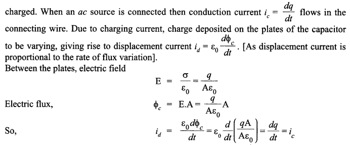
Displacement current brings continuity in the flow of current between the plates of the capacitor.
Answer 15.
(i)
![]()
Here, M and B have the same direction
![]()
(ii)
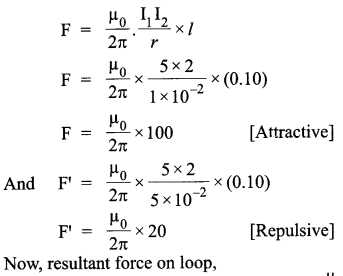

The direction of net force is towards the straight wire i.e., attractive.
Answer 16.
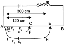
(i) Apply Kirchhoff’s law in loop ACFGA :
K(120) = ε1 – ε2
K = potential drop per unit length or,
ε1 = ε2 + K (120) ……………….. (1)
For loop AEHIA :
K (300) = ε1 + ε2
By substituting value of ε1 from equation (1),
ε1 + ε2 + K (120) = K (300)
2ε2 = K (300 – 120)
2ε2 = 90K ……………….. (2)
Thus,
ε1 = 90K + 120K
ε1 ⇒ 210K ……………….. (3)

ε = Kl
(ii) As we know,
Thus, from equation (2) and (3),
Null point for cell ε2 is 90 cm
And for cell ε1, it is 210 cm.
Sensitivity of the potentiometer can be increased by:
- Increasing the length of the potentiometer wire.
- Decreasing the resistance in the primary circuit.
OR
Apply Kirchhoff’s law in loop ABEFA :
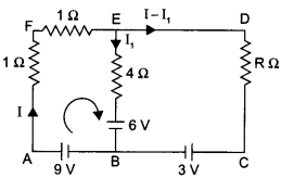
I + I + 4 I1 = 9 – 6
2I + 4 I1 = 3 ……………….. (1)
As there is no current flowing through the 4 Ω resistance.
I1 = 0
or,
2I = 3
or,
⇒ I = 1.5 A
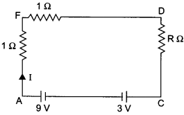
Thus, the current through resistance R is 1.5 A. As there is no current through branch EB, thus equivalent circuit will be, By applying Kirchhoff’s loop law in AFDCA, we get
1.5 +1.5 + R (1.5) = 9-3
⇒ R = 2 Ω
Potential difference between A and D = I x R
= 1.5 x 2 = 3V
Answer 17.
Factors needed for modulating a signal :
(i) To send the signal over large distance for communication.
(ii) Practical size of antenna.

Answer 18.
The current in the forward bias is due to majority carriers where as current in the reverse bias is due to minority carriers. So current in forward bias is more (~ mA) than current in reverse bias (~ μA). On illumination of photodiodes with light, the fractional change in the majority carriers would be much less than that in minority carriers. It implies fractional change due to light on minority carrier dominated reverse bias current is more easily measurable than fractional change in forward bias current f. So photodiodes are operated in reverse bias condition.
Answer 19.
Answer 20.
Einstein’s photoelectric equation,
Where,
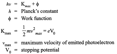
According to Planck’s quantum theory, light radiations consist of small packets of energy. Einstein postulated that a photon of energy hv is absorbed by the electron of the metal surface, then the energy equal to Φ is used to liberate electron from the surface and rest of the energy hv – Φ becomes the kinetic energy of the electron.
∴ Energy of photon is,
Where,
E = hv
h = Planck’s constant
v = frequency of light
The minimum energy required by the electron of a material to escape out of it, is work function ‘Φ’.
The additional energy acquired by the electron appears as the maximum kinetic energy ‘Kmax’ of the electron.
i.e„ Kmax = hv – Φ
or,
hv = Kmax+ Φ
where
Kmax = eV0
Salient features observed in photoelectric effect :
(i) The stopping potential and hence the maximum kinetic energy of emitted electrons varies linearly with the frequency of incident radiation.
(ii) There exists a minimum cut-off frequency v0, for which the stopping potential is zero.
(iii) Photoelectric emission is instantaneous.
Answer 21.
Given, L = 5.0 H, C = 80 μF, R = 40 Ω, V = 240 V
(i) Resonant angular frequency

(ii) At resonant frequency, we know that the inductive reactance cancels out the capacitive reactance.
Impedance, Z = R = 40 Ω
The current at resonant frequency
![]()
(iii) For rms potential drop across inductor
VL = Irms x XL = Irms x ωL = 6 x 50 x 5 = 1500 V.
Answer 22.
(i) The constancy of BE/A over most of the range is saturation property of nuclear force,
In heavy nuclei : nuclear size > range of nuclear force. So, a nuclear sense approximately a constant number of neighbours and thus, the nuclear BE/A levels off at high ‘A’. This is saturation of the nuclear force.
(ii) To find the density of nucleus of an atom, we have an atom with mass number let say A and let mass of the nucleus of the atom of the mass number A be mA.
Let radius of nucleus is R.
SECTION : D
Answer 23.
(i) Sense of responsibility, leadership, general awareness.
(ii) A metal detector is a LCR circuit tuned to resonance. When any person walks through the metal detector gate with any metal, impedance of the circuit changes which is detected by electronic circuit and alarm sounded and security personnels become alert.
SECTION : E
Answer 24.
(i) The new electric field between the plates is,
![]()
The electric field remains unchanged.
(ii) Capacitance becomes half, i.e.,

As the battery has been disconnected, charge can neither be added nor removed. Increasing the distance to double, the value will decrease the capacitance to half. Hence, charge stored will be same.
(iii) Energy stored increases as Q remains the same but the capacitance decreases,
OR
(a) Electric flux :
It is the number of electric field lines passing through a surface normally.

(b) Consider a uniformly charged infinite plane sheet of charge density σ. We have to find electric field E at point P as shown in figure. Now, we construct a Gaussian surface as shown in figure in the form of cylinder.
Applying Gauss’s law,
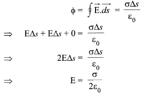
It shows that electric field is uniform due to charged infinite plane sheet. Also, we can say that E is independent of distance from the sheet.
(c)

Direction of field will be towards the sheet if sheet is negatively charged.
Answer 25.
Magnifying power of a telescope is defined as the ratio of the angle subtended at the eye by the image formed at the least distance of distinct vision to the angle subtended at the eye by the object lying at infinity, when seen directly. The formula for
magnifying power is
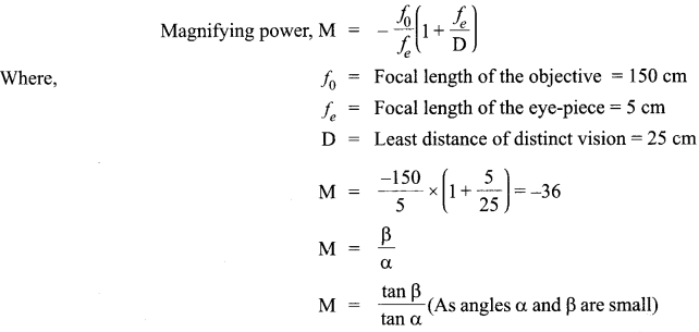
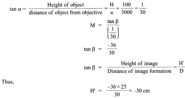
Negative sign indicates that we get an inverted image.
OR
A microscope is used to look into smaller objects like structure of cells etc. On the other hand, a telescope is used to see larger objects that are very far away like stars, planets etc. Telescope mainly focuses on collecting the light into the objective lens, which should thus be large, whereas the microscope already has a focus and the rest is blurred around it. There is a big difference in their magnification factors.
For telescope the angular magnification is given as
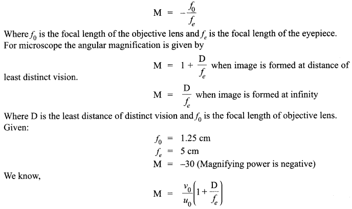
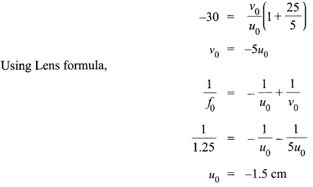
Thus the distance of object from objective is 1.5 cm.
Answer 26.
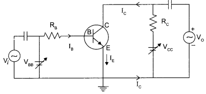
Circuit diagram of CE transistor amplifier :
Working :
If a small sinusoidal voltage is applied to the input of a CE configuration, the base current and collector current will also have sinusoidal variations. Because the collector current drives the load, a large sinusoidal voltage Vo will be observed at the output.
The expression for voltage gain of the transistor in CE configuration is:
Current gain of the transistor will decrease if the base is made thicker because current gain,

If the base of an n-p-n transistor is made thicker, then more and more electrons will recombine with the p-type material of the base. This results in a decrease in collector current Ic. Furthermore, Ib also increase.

Finding expression for voltage gain of the amplifier :
Applying Kirchhoff’s law to the output loop,
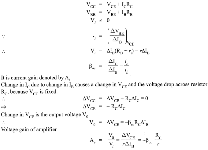
Negative sign represents that the output voltage is opposite with reference to that of input voltage.
OR
(a) Full wave rectifier :
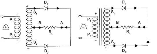
Working : When the diode rectifies the whole of the AC wave, it is called full wave rectifier. The figure shows the arrangement for using diode as full wave rectifier. The alternating input signal is fed to the primary P1P2 of a transformer. The output signal appears across the load wave resistance RL.
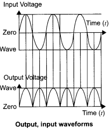
During the positive half of the input signal, suppose P1 and P2 are negative and positive respectively. This would mean that S1 and S2 are positive and negative respectively. Therefore, the diode D1 is forward biased and D2 is reverse biased. The flow of current in the load resistance RL is from A to B. During the negative half of the input signal, S, and S2 are negative and positive respectively. Therefore, the diode D1 is reverse biased and D2 is forward biased. The flow of current in the load resistance RL is from A to B.
(b) Output waveforms (Y) :
We hope the CBSE Sample Papers for Class 12 Physics Paper 5 help you. If you have any query regarding CBSE Sample Papers for Class 12 Physics Paper 5, drop a comment below and we will get back to you at the earliest.