By going through these CBSE Class 12 Physics Notes Chapter 4 Moving Charges and Magnetism, students can recall all the concepts quickly.
Moving Charges and Magnetism Notes Class 12 Physics Chapter 4
→ An electric charge at rest produces an electric field around it while a moving charge produces both electric and magnetic fields.
→ A magnet at rest produces a magnetic field around it.
→ An oscillating, as well as an accelerated charge, produces e.m. waves.
→ No poles are produced in a coil carrying current but such a coil shows N and S polarities.
→ 1T = 104 G = 1 Wb m-2 = 104 maxwell cm-2.
→ A current-carrying conductor has a magnetic field and not an electric field around it.
→ Work done in moving a unit pole around a long conductor is
W = μ0 I
→ The torque acting on the loop is independent of its shape but depends on the area of the loop.
→ Path of a charged particle in a magnetic field ( \(\overrightarrow{\mathrm{B}}\) ) is a straight line when it moves parallel or anti-parallel to \(\overrightarrow{\mathrm{B}}\) and is a circle when moves perpendicular to \(\overrightarrow{\mathrm{B}}\)
→ Two parallel conductors with currents in the same direction attract each other which is a magnetic interaction and if the current flows in them in opposite direction, then they repel each other.
→ Magnetic force is always normal to the field.
→ Magnetic force is not a central force.
→ A long straight current-carrying cylinder for an external point behaves like a straight current-carrying wire.
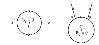
→ If the battery is connected to two points A and B of a conducting ring, the magnetic field at the center due to the current in the ring is zero.
→ A long coil of wire is called a solenoid. Its magnetic field is similar to that of the magnet.
→ The electric field is conservative in nature and ∮ \(\overrightarrow{\mathrm{E}}\).\(\overrightarrow{\mathrm{dl}}\)= 0 but the magnetic field is not conservative as ∮ \(\overrightarrow{\mathrm{B}}\). \(\overrightarrow{\mathrm{dl}}\) = μ0 I.
→ The total force on a planar current loop in a magnetic field is always zero.
→ The radius of a charged particle moving in a magnetic field is directly proportional to its momentum.
→ Speed or K.E. of the particle always remains constant in \(\overrightarrow{\mathrm{B}}\) as \(\overrightarrow{\mathrm{F}_{\mathrm{m}}}\) is perpendicular to \(\overrightarrow{\mathrm{B}}\) .
→ The nature of a circular path followed by a charged particle moving in a given magnetic field depends upon the following:
- Direction of \(\overrightarrow{\mathrm{B}}\),
- The direction of motion of the charged particle,
- Nature of charge.
→ For a positively charged particle moving towards RHS in a downward \(\overrightarrow{\mathrm{B}}\), the circular path is anticlockwise and for a negatively charged particle, it is clockwise.
→ The \(\overrightarrow{\mathrm{B}}\) is uniform (except near the ends) for a sufficiently long solenoid and is independent of its length and area of cross-section.
→ Cyclotron cannot be used to accelerate electrons.
→ A galvanometer is a low resistance instrument.
→ It can be converted into an ammeter by connecting a small resistance parallel to it.
→ Ammeter is always connected in series in the circuit.
→ A galvanometer is converted into a voltmeter by connecting a high resistance in series. The voltmeter is always connected in parallel to the circuit.
→ Two parallel streams of protons with protons moving in the same direction repel each other. There is an electric as well as magnetic interaction. The electric interaction gives repulsive force while the magnetic interaction gives an attractive force. As Fe > Fm, so there is a net repulsion between them.
→ When the above raid stream moves in the opposite direction, then they repel each other.
→ Fe and Fm being repulsive, so there is a net repulsive force between them.
→ The minimum potential difference across the terminals of the galvanometer for full-scale deflection is
Vg = Ig G.
→The potential diff. V across the terminals of a combination of R and G is V = Ig (R + G).
→ \(\frac{\mathrm{V}}{\mathrm{V}_{\mathrm{g}}}=\frac{\mathrm{R}-\mathrm{G}}{\mathrm{G}}\) is called voltage multiplying power of series resistance R and denoted as n.
∴ n = \(\frac{V}{V_{g}}=\frac{R+G}{G}\) ⇒ R = G (n – 1).
→ Rv = R + G = nG.
→ Fleming’s left-hand rule helps us to know the direction of the force on a moving charge or on a current-carrying conductor placed in a uniform magnetic field.
→ Current element: It is the product of current and the length of conductor carrying current i.e., current element = I. \(\overrightarrow{\mathrm{l}}\) .It is a vector quantity acting along I.
→ The direction in a magnetic field along which the current-carrying conductor experiences no force is called the direction of the magnetic field.
→ Pitch of the helix (p): It is defined as the distance traveled by the particle along the magnetic field in one revolution i.e., in a time T.
∴ p = υ cos θ × T = υ cos θ. \(\frac{2 \pi m}{B q}=\frac{2 \pi m v \cos \theta}{B q}\)
→ Shunt: It is a small resistance connected in parallel to the galvanometer.
Important Formulae
→ \(\overrightarrow{\mathrm{B}}\) due to a straight current carrying conductor is given by
\(\overrightarrow{\mathrm{B}}\) = \(\frac{\mu_{0} \mathrm{I}}{4 \pi \mathrm{a}}\)(sin Φ1 + sin Φ2)
→ For infinitely long conductor,
\(\overrightarrow{\mathrm{B}}\) = \(\frac{\mu_{0}}{4 \pi} \cdot \frac{2 \mathrm{I}}{\mathrm{a}}\)
where a = perpendicular distance of the point from the conductor
I = current in the conductor
→ \(\overrightarrow{\mathrm{B}}\) at a point on the axis of a current carrying loop of n turns at a distance x from its centre is given by
\(\overrightarrow{\mathrm{B}}\) = \(\frac{\mu_{0} \mathrm{nIR}^{2}}{2\left(\mathrm{x}^{2}+\mathrm{R}^{2}\right)^{\frac{3}{2}}}\)
where R = radius of loop
→ \(\overrightarrow{\mathrm{B}}\) at its centre is given by
B = \(\frac{\mu_{0} \mathrm{nIR}^{2}}{2 \mathrm{R}^{3}}=\frac{\mu_{0} \mathrm{nI}}{2 \mathrm{R}}\)
→ Magnetic field inside a solenoid having n tums/length is given by
B = µ0 nI.
→ \(\overrightarrow{\mathrm{B}}\) at a point near its end is given by
B = \(\frac{1}{2}\) µ0 nI
→ Maximum energy attained by a particle in a cyclotron is:
Emax = \(\frac{\mathrm{e}^{2} \mathrm{~B}^{2} \mathrm{r}_{\max }^{2}}{2 \mathrm{~m}}\)
→ Potential difference required to accelerate an electron is
V = \(\frac{B^{2} r^{2} e}{2 m}\)
→ Force on a charge moving in \(\overrightarrow{\mathrm{B}}\) is
\(\overrightarrow{\mathrm{F}_{\mathrm{m}}}\) = q(\(\overrightarrow{\mathrm{υ}}\) × \(\overrightarrow{\mathrm{B}}\))
Fmax = qυB
→ Force between two moviiig dia rges s
F = \(\frac{\mu_{0}}{4 \pi} \cdot \frac{\mathrm{q}_{1} \mathrm{q}_{2} v_{1} v_{2}}{\mathrm{r}^{2}}\)
→ Force per unit length between two infinitely long current carrying parallel conductors is
F = \(\frac{\mu_{0}}{4 \pi} \cdot \frac{2 \mathrm{I}_{1} \mathrm{I}_{2}}{\mathrm{r}}\)
→ qυB = \(\frac{\mathrm{m} v^{2}}{\mathrm{r}}\) ⇒ r = \(\frac{\mathrm{m} v}{\mathrm{q} \mathrm{B}}\)
→ Time period, T = \(\frac{2 \pi m}{B q}\)
→ \(\overrightarrow{\mathrm{B}}\) due to current carrying conductor is
B = \(\frac{\mu_{0}}{4 \pi}\).\(\frac{\mathrm{Id} l \sin \theta}{\mathrm{r}^{2}}\)
or
\(\overrightarrow{\mathrm{B}}\) = \(\frac{\mu_{0}}{4 \pi} \cdot \frac{\mathrm{I} \overrightarrow{\mathrm{d} l} \times \hat{\mathrm{r}}}{\mathrm{r}^{2}}=\frac{\mu_{0}}{4 \pi} \cdot \frac{\mathrm{I} \overrightarrow{\mathrm{d} l} \times \overrightarrow{\mathrm{r}}}{\mathrm{r}^{3}}\)
→ G.Ig = (I – Ig)S.⇒ S = \(\frac{\mathrm{I}_{\mathrm{g}} \mathrm{G}}{\mathrm{I}-\mathrm{I}_{\mathrm{g}}}\)
→ V = Ig(G + R).
→ RA = ammeter resistance = \(\frac{\mathrm{GS}}{\mathrm{G}+\mathrm{S}}\)
→ Voltmeter resistance = RV = G + R
→ No. of revolutions per second = \(\frac{\text { speed }}{\text { circumference }}=\frac{v}{2 \pi r}\)
→ I = ne, where n = \(\frac{\mathrm{v}}{2 \pi \mathrm{r}}\)
→ Force on current carrying conductor in a \(\overrightarrow{\mathrm{B}}\) is, F = BIl sin θ
→ Fmax = BIl if θ = 90°.
→ Current sensitivity = \(\frac{\theta}{I}=\frac{N A B}{k}\)
→ Voltage sensitivity = \(\frac{\theta}{\mathrm{V}}=\frac{\theta}{\mathrm{IR}}=\frac{\mathrm{SI}}{\mathrm{R}}=\frac{\mathrm{NAB}}{\mathrm{kR}}\)
→ Torque on a current carrying coil in \(\overrightarrow{\mathrm{B}}\)is τ = nBAI sin θ = nBIA cos α where θ = angle made by \(\overrightarrow{\mathrm{B}}\) with the normal to the plane of coil and
α = angle made by \(\overrightarrow{\mathrm{B}}\) with the plane of coil.