By going through these CBSE Class 12 Physics Notes Chapter 7 Alternating Current, students can recall all the concepts quickly.
Alternating Current Notes Class 12 Physics Chapter 7
→ In a pure ohmic resistance both alternating current and e.m.f. are in the same phase.
→ Alternating e.m.f. leads the alternating current by \(\frac{π}{2}\) in a pure inductance.
→ In a pure capacitor circuit, the alternating e.m.f. lags behind the alternating current by \(\frac{π}{2}\).
→ xL = ωL is called inductive reactance.
→ xC = \(\frac{1}{\omega C}\) is called capacitance reactance.
→ Resistance, reactance, and impedance all are measured in ohm.
→ The graph between xL and ω is a straight line.
→ The applied voltage is equal to the potential drop across the resistance R at the resonant frequency in the LCR circuit.
→ Power is dissipated only due to the ohmic resistance in an a.c. circuit.
→ Thus in an RC or RL a.c. the circuit power is dissipated only due to R and not due to its inductance or capacitance.
→ Resonant angular frequency is the same both for the series and parallel resonant circuit.
→ The graph between xC and w is a hyperbola.
→ The maximum value of current is I = \(\frac{E_{\mathrm{rms}}}{\mathrm{R}}\)at the resonant angular frequency W = W0.
→ As ω to increases, Z of parallel LCR resonant circuit first increases becomes maximum and then decreases.
→ For series LCR resonant circuit, Z first decreases become minimum and then increases.
→ The power rating of an element used in a.c. circuit refers to its average power rating.
→ The power consumed in an a.c. the circuit is never negative.
→ For very high frequency of a.c., the inductor behaves as an open circuit and the capacitor behaves as a conductor.
→ The impedance of the LR circuit depends upon the frequency of a.c. The phase angle between E and I in an LR circuit also depends upon the frequency.
→ As the frequency of a.e. increases, the impedance of the CR circuit decreases.
→ Electrical resonance takes place when the amplitude of the current in the circuit is maximum and impedance is minimum and the LCR circuit is a purely resistive circuit.
→ For purely resistive circuit, power factor = 1.
→ For purely inductive and capacitive circuits, the power factor is zero. Choke coil is used to control a.c. without much loss of electric power.
→ K > 1 for step-up transformer and K < 1 for step down transformer. Transformer works on the principle of mutual inductance. q = 100% and Eplp = EsIs for an ideal transformer.
→ The power consumed in a circuit is never negative.
→ A.C.: It is defined as the? electric current magnitude of which changes with time and reverses its direction periodically.
→ Average or Mean Value of A.C.: It is defined as that steady current which when passed through a circuit for a half time period of A.C. produces the same amount of charge as is being produced by A.C. in the same time and in the same circuit.
→ R.M.S. value or effective value of A.C.: It is defined as that steady current that produces the same amount of heat in resistance in a given time as is being done by a.c. passed through the same circuit for the same time.
→ Inductive reactance: It is the effective opposition offered by the inductor to the flow of a.c. in the circuit.
→ Capacitive reactance: -It is the effective opposition offered by the capacitor to the flow of a.c. in the circuit.
→ Q-factor of series LCR circuit: It is defined as the ratio of the voltage drop across inductor (or capacitor) to the applied voltage.
→ Power of an a.c. circuit: It is the product of instantaneous e.m.f. and instantaneous current in the circuit.
→ Power factor: It is defined as the ratio of average power to the apparent power.
→ Idle or wattless current: It is the current due to the flow of which no power is consumed in an a.c. circuit.
→ Transformer’s a device used to convert low alternating voltage at high current into a high voltage at low current or vice-versa.
Important Formulae
→ Erms = \(\frac{1}{\sqrt{2}}\) E0 = E virtual = Eeff
→ Irms = \(\frac{1}{\sqrt{2}}\) I0
→ Instantaneous e.m.f. is given by E = E0 sin ωt
→ In a purely inductive circuit, current lags behind E by \(\frac{π}{2}\)
I = I0 sin (ωt – \(\frac{π}{2}\))
→ In a purely capacitive circuit
I = I0 sin (ωt + \(\frac{π}{2}\))
→ XL = ωL = 2πvL = \(\frac{\mathrm{E}_{0}}{\mathrm{I}_{0}}=\frac{\mathrm{E}_{\mathrm{v}}}{\mathrm{F}_{v}}\)
→ XL = \(\frac{1}{\omega C}=\frac{1}{2 \pi v C}=\frac{E_{0}}{I_{0}}=\frac{E_{v}}{I_{v}}\)
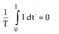
→ Average value of induced a.c. over a complete cycle is:
→ Average power = apparent power × power factor
or
Pav = Ev Iv cos Φ.
→ cos Φ = \(\frac{\mathrm{R}}{\mathrm{Z}}\)
→ Resonant angular frequency of LCR series circuit is given by
ω0 = \(\frac{1}{\sqrt{\mathrm{LC}}}\)
or
v0 = \(\frac{1}{2 \pi \sqrt{L C}}\)
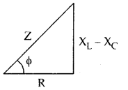
→ Impedence of LCR series circuit is given by
Z = \(\sqrt{R^{2}+\left(X_{L}-X_{C}\right)^{2}}\)
= \(\sqrt{R^{2}+\left(\omega L-\frac{1}{\omega C}\right)^{2}}\)
→ Tangent of the phase angle is given by .
tan Φ = \(\frac{X_{L}-X_{C}}{R}\)
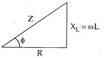
→ Power factor of LR circuit is given by
cos Φ = \(\frac{R}{Z}=\frac{R}{\sqrt{R^{2}+X_{L}^{2}}}\)
tan Φ = \(\frac{\mathrm{x}_{\mathrm{L}}}{\mathrm{R}}=\frac{\omega \mathrm{L}}{\mathrm{R}}\)
→ For CR. circuit,
tan Φ = \(\frac{X_{C}}{R}=\frac{1}{R \omega C}\)
Z = \(\sqrt{R^{2}+X_{c}^{2}}=\sqrt{R^{2}+\left(\frac{1}{\omega C}\right)^{2}}\)
→ For a transformer,
K = \(\frac{\mathrm{N}_{\mathrm{s}}}{\mathrm{N}_{\mathrm{p}}}=\frac{\phi_{\mathrm{s}}}{\dot{\phi}_{\mathrm{p}}}=\frac{\mathrm{E}_{\mathrm{s}}}{\mathrm{E}_{\mathrm{p}}}=\frac{\mathrm{I}_{\mathrm{p}}}{\mathrm{I}_{\mathrm{s}}}\)
→ For an ideal transformer,
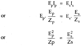
When Zp and Zs are called impedance of primary and secondary coil of the transformer.
→ Efficiency of a transformer is given by,
η = \(\frac{\text { output power }}{\text { input power }}\)
= \(\frac{\mathrm{E}_{\mathrm{s}} \mathrm{I}_{\mathrm{s}}}{\mathrm{E}_{\mathrm{p}} \mathrm{I}_{\mathrm{p}}}\).
→ Maximum e.m.f. induced in a coil is given by e0 = NBAω.
where N = No. of turns of the coil.
A = Area of the coil.
ω = angular frequency of rotation of the coil.
B = magnetic field.
→ Q.factor = \(\frac{\mathrm{X}_{\mathrm{L}} \mathrm{I}}{\mathrm{RI}}=\frac{\omega_{0} \mathrm{~L}}{\mathrm{R}}=\frac{1}{\omega_{0} \mathrm{CR}}=\frac{1}{\mathrm{R}} \sqrt{\frac{\mathrm{L}}{\mathrm{C}}}\)