Here we are providing Class 12 Physics Important Extra Questions and Answers Chapter 4 Moving Charges and Magnetism. Important Questions for Class 12 Physics with Answers are the best resource for students which helps in Class 12 board exams.
Class 12 Physics Chapter 4 Important Extra Questions Moving Charges and Magnetism
Moving Charges and Magnetism Important Extra Questions Very Short Answer Type
Question 1.
Under what condition is the force acting on a charge moving through a uniform magnetic field minimum?
Answer:
When the charge moves parallel to the direction of the magnetic field.
Question 2.
What Is the nature of the magnetic field in a moving coil galvanometer?
Answer:
Radial magnetic field.
Question 3.
State two properties of the material of the wire used for suspension of the coil in a moving coil galvanometer.
Answer:
- High tensile strength.
- SmalL vaLue of torque per unit twist.
Question 4.
Write one condition under which an electric charge does not experience a force in a magnetic field.
Answer:
When it moves parallel to the direction of the magnetic field.
Question 5.
Mention the two characteristic properties of the material suitable for making the core of a transformer. (CBSE AI 2012)
Answer:
- Low retentivity
- High permeability
Question 6.
Write the expression, in a vector form, for the Lorentz magnetic force due to a charge moving with velocity \(\vec{V}\) in a magnetic field \(\vec{B}\). What is the direction of the magnetic force? (CBSE Delhi 2014)
Answer:
The expresion is \(\vec{F}\) = q(\(\vec{V}\) × \(\vec{B}\)). The force is perpendicular to both the velcoity and the magentic field vector.
Question 7.
Write the condition under which an electron will move undeflected in the presence of crossed electric and magnetic fields. (CBSE Al 2014C)
Answer:
An electron moves perpendicular to both fields.
Question 8.
What can be the cause of the helical motion of a charged particle? (CBSE Al 2016)
Answer:
The charge enters the magnetic field at any angle except 0°, 180°, and 90°.
Question 9.
Write the underlying principle of a moving coil galvanometer. (CBSE Delhi 2016)
Answer:
A current-carrying loop placed in a magnetic field experiences a torque.
Question 10.
A proton and an electron traveling along parallel paths enter a region of the uniform magnetic field, acting perpendicular to their paths. Which of them will move in a circular path with a higher frequency? (CBSEAI and Delhi 2018)
Answer:
The frequency of revolution is given by
v = \(\frac{B q}{2 \pi m}\) ⇒ v ∝ \(\frac{1}{m}\) .
As for me < mp
therefore ve >vp
Question 11.
Two protons of equal kinetic energies enter a region of the uniform magnetic field. The first proton enters normal to the field direction while the second enters at 30° to the field direction. Name the trajectories followed by them. (CBSEAI and Delhi 2018C)
Answer:
Normal: circular
At an angle of 30°, it will follow a helical path.
Question 12.
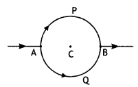
Consider the circuit shown here where APB and AQB are semi-circles. What will be the magnetic field at the center C of the circular loop?
Answer:
Zero, because magnetic fields due to APB and AQB are equal in magnitudes but opposite in directions.
Question 13.
Which one of the following will have a minimum frequency of revolution,
when projected with the same velocity v perpendicular to the magnetic field B: (i) α – particle and (ii) β – particle.
Answer:
Frequency of revolution v = \(\frac{q B}{2 \pi m}\) and \(\frac{q}{m}\) of α – particle is less, hence α – particle will have minimum frequency of revolution.
Question 14.
An ammeter and a milli-ammeter are converted from the same galvanometer. Out of the two, which current-measuring instrument has higher resistance?
Answer:
A milli-ammeter has higher resistance.
Question 15.
Equal currents I and I are flowing through two infinitely long parallel wires. What will be the magnetic field at a point mid-way when the currents are flowing in the same direction?
Answer:
Zero, because fields due to two wires will be equal but opposite.
Question 16.
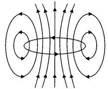
The figure shows a circular loop carrying current l. Show the direction of the magnetic field with the help of lines of
![]()
Answer:
The magnetic field lines are as shown
Question 17.
An electron is moving with velocity v along the axis of a long straight solenoid carrying current I. What will be the force acting on the electron due to the magnetic field of the solenoid?
Answer:
Zero, as a force on a charged particle moving in a magnetic field, is F= Bqv sin θ
Here both v and B are along the axis of – solenoid, so θ = 0° between them. Hence F= qvB sin θ = 0.
Moving Charges and Magnetism Important Extra Questions Short Answer Type
Question 1.
A charged particle having a charge q is moving with a speed of v along the X-axis. It enters a region of space where the electric field is \(\overrightarrow{\boldsymbol{E}}(\boldsymbol{E} \hat{\boldsymbol{j}})\) and a magnetic field \(\vec{B}\) are both present. The particle, on emerging from the region, is observed to be moving, along the X-axis only. Obtain an expression for the magnitude of \(\vec{B}\) in terms of v and E. Give the direction of \(\vec{B}\).
Answer:
Since the particle continues to move along the X-axis, therefore, the magnetic force acting on it should be completely balanced by the electric force. Since the electric force acts along the Y-axis, therefore, the magnetic force must be along the Z-axis.
Thus is equilibrium q E = B q v or v = E/B
Question 2.
A stream of electrons traveling with speed v m s-1 at right angles to a uniform magnetic field ‘B’ is reflected in a circular path of radius ‘r’ . Prove that \(\frac{e}{m}=\frac{v}{r B}\)
Answer:
Let a stream of electrons be traveling with speed v at right angles to a uniform magnetic field B then force due to magnetic field provides the required centripetal force which deflects the electron beam along a circular path of radius ‘r’ such that
Bev = \(\frac{m v^{2}}{r}\)
or
\(\frac{e}{m}=\frac{v}{r B}\)
where e = electronic charge and m = mass of the electron.
Question 3.
Which one of the two, an ammeter or a milliammeter, has a higher resistance and why?
Answer:
The shunt resistance connected to convert a galvanometer into an ammeter or a milliammeter is given by the expression S = \(\frac{I_{g} G}{I-l_{g}}\) where S is shunt resistance, G galvanometer resistance, l total current through G and S, and lg galvanometer current. In the case of milliammeter, l is small.
Therefore Smilliammeter > Sammeter . Hence the resistance of a milliammeter is greater than that of an ammeter.
Question 4.
A straight wire of length L carrying a current l stays suspended horizontally in mid-air in a region where there is a uniform magnetic field \(\vec{B}\). The linear mass density of the wire is l. Obtain the magnitude and direction of the magnetic field.
Answer:
The magnetic force acting on the straight wire balances the weight of the wire.
Therefore, in equilibrium we have Mg = BIL, here M = L l, therefore we have L l g = BlL or B = l/ l g
This field acts vertically upwards.
Question 5.
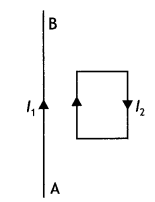
In the figure below, the straight wire AB Is fixed while the loop Is free to move under the influence of the electric currents flowing in them. In which direction does the loop begin to move? Give a reason for your answer.
Answer:
The loop moves towards the straight wire AB. In the loop in the side nearer to the wire AB current l2 is in the same direction as l1 and hence attractive force acts. However, on the side farther away from the wire AB current l2 is in the opposite direction and the force is repulsive. But as the magnitude of attractive force is greater than the repulsive force, the net force is attractive in nature and hence, the loop moves towards the wire AB.
Question 6.
A coil of ‘N’ turns and radius ‘R’ carries a current ‘l’. It is unwound and rewound to make a square coil of side ‘a’ having the same number of turns (N). Keeping the current ‘l’ same, find the ratio of the magnetic moments of the square coil and the circular coil. (CBSE Delhi 2013C)
Answer:
The magnetic moment of a current loop is given by the relation M = nlA
For the circular loop Mc = NlπR² …(1)
Now when the coil is unwound and rewound to make a square coil, then
2 πR = 4a or a = πR/2
Hence magnetic moment of the square coil is
Ms = Nl a² = Nl (πR/2)² = Nl π²R²/4 …(2)
From (1) and (2) we have
\(\frac{M_{S}}{M_{C}}=\frac{N l \pi^{2} R^{2} / 4}{N l \pi R^{2}}=\frac{\pi}{4}\)
Question 7.
Write the expression for Lorentz magnetic force on a particle of charge ‘q’ moving with velocity v in a magnetic field B. Show that no work is done by this force on the charged particle. (CBSE Al 2011)
Answer:
The expression is \(\vec{F}\) = q(\(\vec{v}\) × \(\vec{B}\)). This force always acts perpendicular to the direction of motion of the charged particle. Therefore the angle between \(\vec{F}\) and \(\vec{r}\) is 90°. Hence work done is W = \(\vec{F}\). r = Fr cos 90° = 0
Question 8.
(a) State Biot-Savart law in vector form expressing the magnetic field due to an element \(\vec{dl}\) carrying current l at a distance \(\vec{r}\) from the element.
Answer:
It states that for a small current element dl the magnetic field at a distance r is given by
\(\overrightarrow{d B}=\frac{\mu_{0}}{4 \pi} \frac{I \overline{(d L} \times \hat{r})}{r^{2}}\).
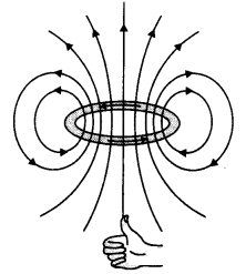
(b) Write the expression for the magnitude of the magnetic field at the center of a circular loop of radius r carrying a steady current l. Draw the field lines due to the current loop. (CBSE Al 2014C)
Answer:
The magnetic field at the center of a circular loop is given by
B = \(\frac{\mu_{0} l}{2 r}\)
The field lines are as shown.
Question 9.
Draw the magnetic field lines due to current passing through a long solenoid. Use Ampere’s circuital law, to obtain the expression for the magnetic field due to the current l in a long solenoid having n number of turns per unit length. (CBSE Delhi 2014C)
Answer:
The diagram is as shown.
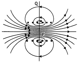
Consider a rectangular path abed of length L as shown in the figure below. Let us apply Ampere’s circuital law to this rectangular path so that we have
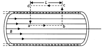
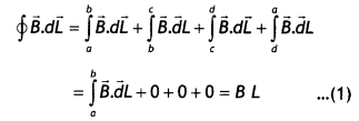
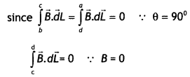
But by Ampere’s circuital law we have
\(\oint \vec{B} \cdot \vec{d} L\) = μ0Nl = μ0(nL)l …(2)
From equations (1) and (2) we have
BL = μ0nLl
or
B = μ0 n l
But n = N/L, therefore we have
B = μ0 \(\frac{N l}{L}\)
This gives the value of a magnetic field inside a solenoid.
Question 10.
(a) Why do we use a shunt to convert a galvanometer into an ammeter?
Answer:
Since an ammeter is an instrument used to measure the current in the circuit, so it has to be connected in series in the circuit to measure the whole current. Hence its resistance must below. A low shunt resistance makes it suitable for measuring current.
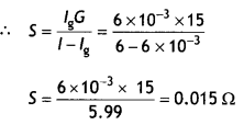
(b) A galvanometer of resistance 15 Ω shows a full-scale deflection on the meter scale for a current of 6 mA. Calculate the value of the shunt resistance required to convert the galvanometer into an ammeter of range 0-6 A. (CBSE 2019C)
Answer:
Given G = 15 Ω, lg = 6 mA = 6 × 10⁻³ A, l = 6 A, S = ?
Question 11.
An electron beam projected along + X-axis experiences a force due to a magnetic field along the + Y-axis. What is the direction of the magnetic field?
Answer:
The direction of the magnetic field is along Z-axis. This is because the direction of motion, the magnetic field, and the force are perpendicular to one other as an electron carries a negative charge.
Question 12.
A current is set up in a long copper pipe. Is there a magnetic field
(i) inside,
Answer:
There is no magnetic field inside the pipe.
(ii) outside the pipe?
Answer:
There is a magnetic field outside the pipe.
Question 13.
Which one of the following will experience a maximum force, when projected with the same velocity V perpendicular to the magnetic field (i) alpha particle and (ii) beta particle?
Answer:
The force experienced by a charged particle is given by the expression F = B q v. Since an alpha particle has a moving charge than the beta particle, therefore the alpha particle will experience more force.
Question 14.
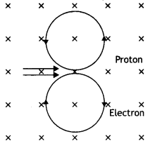
An electron and a proton moving parallel to each other in the same direction with equal momenta enter into a uniform magnetic field which is at right angles to their velocities. Trace their trajectories in the magnetic field.
Answer:
Because both electron and proton have the same charge and momentum, therefore they will describe circles of equal radii as shown.
Question 15.
Is the steady electric current the only source of the magnetic field? Justify your answer. (CBSE Delhi 2013C)
Answer:
No, the magnetic field is also produced by alternating current.
Question 16.
A deuteron and an alpha particle having the same momentum is in turn allowed to pass through a magnetic field B, acting normal to the direction of motion of the particles. Calculate the ratio of the radii of the circular paths described by them. (CBSE Delhi 2019)
Answer:
Pd = Pα
Now r = \(\frac{mv}{Bq}\) ⇒ r ∝ \(\frac{1}{q}\)
Therefore, \(\frac{r_{d}}{r_{\alpha}}=\frac{q_{\alpha}}{q_{d}}=\frac{2 e}{e}\) = 2
Question 17.
Two wires of equal length are bent in the form of two loops. One of the loops is square-shaped and the other is circular. These are suspended in a uniform magnetic field and the same current is passed through them. Which loop will experience a greater torque? Give reasons.
Answer:
Torque experienced by a current-carrying loop placed in a uniform magnetic field is given by the expression τ = BlnA. In other words, torque is directly proportional to the area of the loop. Since a circular wire has more area than a square wire for the same dimension, therefore the circular wire experiences more torque than the square wire.
Question 18.
Which one of the following will have a minimum frequency of revolution, when projected with the same velocity v perpendicular to the magnetic field B: (i) alpha particle and (ii) beta particle?
Answer:
The frequency of revolution of a charged particle in a magnetic field is given by Bq
v = \(\frac{Bq}{2πm}\).
The ratio of q/m for an alpha particle is less than that for a beta particle; therefore, the alpha particle will have a minimum frequency of revolution.
Question 19.
Using the concept of force between two infinitely long parallel current-carrying conductors, define one ampere of current. (CBSE AI 2014)
Answer:
One ampere is that much current which when flowing through each of the two infinitely long straight conductors held 1 meter apart in space, produce a force of F= 2 × 10⁻⁷ N per meter of their length.
Question 20.
(a) Write the expression for the force \(\vec{F}\) , acting on a charged particle of charge ‘q’, moving with a velocity v in the presence of both electric field \(\vec{E}\) and magnetic field \(\vec{B}\) . Obtain the condition under which the particle moves undeflected through the fields.
Answer:
(a) The required expression is \(\vec{F}=q \vec{E}+q(\vec{v} \times \vec{B})\)
The particle will move undeflected if the force acting on it due to the electric field balances the force acting on it due to the magnetic field. Thus qE = Bqv or v=E/B
(b) A rectangular loop of size l × b carrying a steady current I is placed in a uniform magnetic field \(\vec{B}\) . Prove that the torque τ acting on the loop is given by \(\vec{τ}\) = \(\vec{m}\) × \(\vec{B}\) , where m is the magnetic moment of the loop. (CBSE AI 2012, Delhi 2013)
Answer:
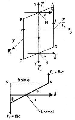
The figure below shows a rectangular loop of wire with length ‘a’ and breadth ‘b’. A line perpendicular to the plane of the loop (i.e. a normal to the plane) makes an angle Φ with the direction of the magnetic field B, and the loop carries a current / as shown. Let the forces acting on the various sides of the loop be \(\vec{F}_{1}\), \(\vec{F}_{2}\), \(\vec{F}_{3}\) and \(\vec{F}_{4}\) as shown.
It follows from the expression for the force experienced by a conductor in a magnetic field that force on arm AB is
\(\vec{F}_{1}=I(\overrightarrow{\mathrm{AB}} \times \vec{B})\) …(1)
(in the plane of the paper and is directed upwards as shown).
The force on arm CD is given by \(\vec{F}_{2}=l(\overrightarrow{\mathrm{CD}} \times \vec{B})\) …(2)
(in the plane of the paper and is directed downwards as shown.)
Since these two forces are equal and opposite and have the same line of action therefore they cancel out each other’s effect and their resultant effect on the coil is zero.
Now the force on arm BC is
\(\vec{F}_{3}=l(\overrightarrow{\mathrm{BC}} \times \vec{B})\) …(3)
(acts perpendicular to the plane of the paper and is directed outwards as shown) Finally the force on arm DA is
\(\vec{F}_{4}=I(\overrightarrow{\mathrm{DA}} \times \vec{B})\) …(4)
(acts perpendicular to the plane of the paper and is directed inwards as shown in figure).
Both forces F3 and F4 make an angle of 90° with the direction of the magnetic field. Therefore, in magnitude, these forces are given by
F3 = F4 = laB sin90° = laB …(5)
The lines of action of both these forces are perpendicular to the plane of the paper. The two forces F3 and F4 lie along different lines and each give rise to a torque about the X-axis. The two torques produce a resultant torque in + X direction. The arm of the couple (perpendicular distance between the lines of action of the two forces) from the figure below is given by
An arm of couple = b Sin Φ …(6)
Therefore, by the definition of torque we have
Torque = either force × arm of couple Using equations (5) and (6) we have
Torque = l B a × b Sin Φ
But a b = A, area of the coil, therefore τ = l B A Sin Φ
Question 21.
Show that a force that does no work must be a velocity-dependent force. (NCERT Exemplar)
Answer:
We know that work is the dot product of force and displacement, therefore
dW = \(\vec{F} \cdot d \vec{l}\) = 0
Or
dW = \(\vec{F}\) .\(\vec{v}\)dt = 0
Or
\(\vec{F} \cdot \vec{v}\) = 0
Thus F must be velocity dependent which implies that the angle between F and v is 90°. If v changes direction then the direction of F should also change so that the above condition is satisfied.
Question 22.
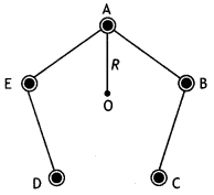
Five long wires A, B, C, D, and E, each carrying current l is arranged to form edges of a pentagonal prism as shown in the figure. Each carries current out of the plane of the paper.
(a) What will be magnetic induction at a point on axis 0? Axis is at a distance R from each wire.
(b) What will be the field if the current in one of the wires (say A) is switched off?
(c) What if the current in one of the wires (say) A is reversed? (NCERT Exemplar)
Answer:
(a) Zero Mn I
(b) \(\frac{\mu_{0}}{2 \pi} \frac{1}{R}\) perpendicular to AO towards left
(c) \(\frac{\mu_{0}}{\pi} \frac{1}{R}\) perpendicular to AO towards left
Moving Charges and Magnetism Important Extra Questions Long Answer Type
Question 1.
(a) A particle of charge ‘q’ and mass ‘m’, moving with velocity \(\vec{v}\) is subjected to a uniform magnetic field \(\vec{B}\) perpendicular to its velocity. Show that the particle describes a circular path. Obtain an expression for the radius of the circular path of the particle.
Answer:
Let a charged particle of charge q and mass m be moving with velocity \(\vec{v}\) right angle to the field (i.e. in the plane of the paper), then magnetic force \(\vec{F}\) acting on the charge q will be
\(\vec{F}=q(\vec{v} \times \vec{B})\)
or
F = qvB sin 90°
or
F = qvB … (1)
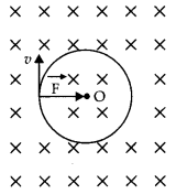
As this forces fact at a right angle to the velocity V of the charged particle, the slot is unable to change the velocity but can make the charged particle move In a circular path.
If r is the radius of the circle, then the centripetal force required by the charged particle will be
\(F_{c}=\frac{m v^{2}}{r}\)
This centripetal force Is provided by the magnetic force acting on the charged particle.
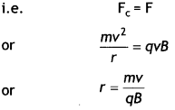
(b) Explain, how its path will be affected if the velocity \(\vec{v}\) makes an angle (θ ≠ 90°) with the direction of the magnetic field. (CBSE 2019C)
Answer:
If (θ ≠ 90°), the velocity \(\vec{v}\) of the moving charge can be resolved into two components v cos θ, in the direction of the magnetic field and make it v sin θ, in the direction perpendicular to the magnetic field. The charged particle under the combined effect of the two components of velocities wilt cover linear as well as a circular path, i.e. helical path whose axis is parallel to the magnetic field.
Question 2.
(a) Obtain the conditions under which an electron does not suffer any deflection while passing through a magnetic field.
Answer:
No deflection suffered by the electron if it moves parallel or anti-parallel to the magnetic field.
(b) Two protons P and Q moving with the same speed pass through the magnetic fields \(\vec{B}_{1}\) and \(\vec{B}_{2}\) respectively, at right angles to the field directions. If \(\left|\vec{B}_{2}\right|>\left|\vec{B}_{1}\right|\), which of the two protons will describe the circular path of smaller radius? Explain. (CBSEAI 2019)
Answer:
The radius of the circular path traveled by a charged particle in a magnetic field is given by
r = \(\frac{mv}{Bq}\)
Therefore, \(\frac{r_{1}}{r_{2}}=\frac{B_{2}}{B_{1}}\)
As \(\left|\vec{B}_{2}\right|>\left|\vec{B}_{1}\right|\) therefore, r2 < r1
Question 3.
A straight wire of length L is bent into a semi-circular loop. Use Biot-Savart law to deduce an expression for the magnetic field at its center due to the current l passing through it. (CBSE Delhi 2011C)
Answer:
Consider a straight wire of length L. Let it be bent into a semicircular arc of radius r as shown,
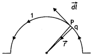
Then πr = L or r = L/π
Let a current I be passed through it. Divide the semi-circular loop into a large number of elements; consider one such element PQ of length dl. Then the small magnetic field cfB produced at the point O is
dB = \(\frac{\mu_{0}}{4 \pi} \frac{l d l \sin 90^{\circ}}{r^{2}}=\frac{\mu_{0}}{4 \pi} \frac{l d l}{r^{2}}\) outwards at point O.
Therefore total magnetic field at point O is
B = \(\int_{0}^{\pi r} \frac{\mu_{0}}{4 \pi} \frac{l d l}{r^{2}}=\frac{\mu_{0} l}{4 r}=\frac{\mu_{0} l \pi}{4 L}\)
Question 4.
A circular coil of N turns and radius R carries a current l. It is unwound and rewound to make another coil of radius R/2, current l remaining the same. Calculate the ratio of the magnetic moments of the new coil and the original coil. (CBSE AI 2012)
Answer:
The magnetic moment of a current-carrying coil is given by
M = n lA = n l πR²
When the coil is unwound and wound into another coil of radius R/2, the number of turns will double, i.e. n = 2
Therefore, n1 = 1, n2 = 2, R1 = R, R2 = R/2, hence
Therefore \(\frac{M_{2}}{M_{1}}=\frac{n_{2} / \pi R_{2}^{2}}{n_{1} / \pi R_{1}^{2}}=\frac{2}{4}=\frac{1}{2}\)
Question 5.
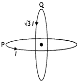
Two identical coils P and Q each of radius R are lying in perpendicular planes such that they have a common center. Find the magnitude and direction of the magnetic field at the common center when they carry currents equal to l and \(\sqrt{3}\) l respectively. (CBSE Al 2019)
Answer:
Magnetic field at the common centre due to coil P
\(B_{1}=\frac{\mu_{o} l}{2 R}\)
Magnetic field at the common centre due to coil Q
\(B_{2}=\frac{\mu_{0} \sqrt{3} l}{2 R}\)
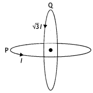
The two fields are mutually perpendicular, therefore, the resultant field at the common centre is
B = \(\sqrt{B_{1}^{2}+B_{2}^{2}}=\sqrt{\left(\frac{\mu_{o} l}{2 R}\right)^{2}+\left(\frac{\mu_{0} \sqrt{3} 1}{2 R}\right)^{2}}\)
= \(\frac{\mu_{o} l}{R}\)
Let the resultant field make an angle θ with magnetic field B<sub>2</sub> as shown
tan θ = \(\frac{B_{1}}{B_{2}}=\frac{1}{\sqrt{3}}\) ⇒ θ = 30°
Question 6.
Find the condition under which the charged particles moving with different speeds in the presence of electric and magnetic field vectors can be used to select charged particles of a particular speed. (CBSE A! 2017)
Answer:
Consider crossed electric and magnetic fields. Let the particle enter perpendicular to both these fields. Due to this, the electric and magnetic forces are in opposite directions. Suppose, we adjust the value of E and B such that the magnitudes of the two forces are equal. Then, the total force on the charge is zero and the charge will move in the fields undeflected.
This happens when, or qE = qvB or v = E/B
This condition can be used to select charged particles of a particular velocity out of a beam containing charges moving at different speeds (irrespective of their charge and mass). The crossed E and B fields, therefore, serve as a velocity selector. Only particles with speed E/B pass undeflected through the region of crossed fields.
Question 7.
(a) Define the SI unit of current in terms of the force between two parallel current-carrying conductors.
Answer:
One ampere is that much current which when flowing through each of the two infinitely long straight conductors held 1 meter apart in space, produces a force of F = 2 × 10⁻⁷ N per meter of their length.
(b) Two long straight parallel conductors carrying steady currents la and lb along the same direction are separated by a distance d. How does one explain the force of attraction between them? If a third conductor carrying a current l in the opposite direction is placed just in the middle of these conductors, find the resultant force acting on the third conductor. (CBSE AI, Delhi 2018C)
Answer:
The magnetic field produced by one current applies a force on the other current-carrying conductor. By Fleming’s left-hand rule the forces acting on each due to other is directed towards each other. This shows attraction.
Force on C conductor due to conductor A
Fca = \(\frac{\mu_{0} l_{a} l_{c}}{\pi d}\) repulsive
Force on C conductor due to conductor B
Fcb = \(\frac{\mu_{0} l_{b} l_{c}}{\pi d}\)
Question 8.
ExplaIn how will you convert a galvanometer into a voltmeter to read a maximum potential of ‘V’ volt. Can one use a voltmeter to measure the emf of a cell? Justify your answer.
Answer:
Suppose a galvanometer having resistance G is to be converted into a voltmeter, which can measure the potential difference from O to V volt. Let a high resistance R be joined in senes with the galvanometer for this purpose. Its value is so chosen that when the galvanometer with the resistance is connected between two points having a potential difference of V volt, the gaLvanometer gives full-scale deflection. It is clear from the figure below that
V = lg (R + G)
or
R = \(\frac{v}{l_{g}}\) – G
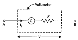
On connecting the above high resistance in series with a galvanometer, the galvanometer is converted into a voltmeter of range V volt.
A voltmeter cannot measure the emf of the cell as it draws current from the cell while measuring the potential differences.
Question 9.
Explain how will you convert a galvanometer into an ammeter to read a maximum current of ‘l’ ampere. An ammeter is always connected in series with a circuit. Why? (CBSE AI 2019)
Answer:
Suppose a galvanometer of resistance G is to be converted into an ammeter having range 0 to l ampere. Let lg be the current,
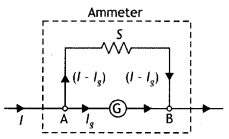
which gives full-scale deflection in the galvanometer. Suppose S is the appropriate shunt required for this purpose, i.e. when shunt S Is used, current ‘g passes through the galvanometer and the remaining (l – lg) passes through the shunt as shown in the figure below. Since the shunt and the galvanometer are connected In parallel therefore the potential differences across both wilL be the same. Hence
lg G = (l – lg) S ….(1)
S = \(\frac{l_{s} G}{l-l_{s}}\) ….(2)
An ammeter is used to measure current; therefore, it is connected in senes so that the entire current passes through it. Moreover, an ammeter is a low resistance device.
Question 10.
A steady current (l1) flows through a long straight wire. Another wlrè carrying steady current (l2) In the same direction is kept close and parallel to the first wire. Show with the help of a diagram how the magnetic field due to the current l1 exerts a magnetic force on the second wire. Write the expression for this force. (CBSE AI 2011)
Answer:
The diagram is as shown below.
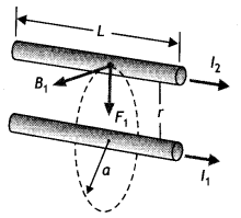
Magnetic field B1 is produced by the wire carrying current l1 on a wire carrying current l2. Thus the second current-carrying wire is placed in the magnetic field produced by the first as a result it experiences a force is given by F = \(\frac{\mu_{0} l_{1} l_{2}}{2 \pi r}\) per unit length.
Question 11.
(a) State Ampere’s circuital law expressing it in the integral form.
(b) Two long coaxial insulated solenoids S1 and S2 of equal lengths are wound one over the other as shown in the figure. A steady current ‘l’ flows through the inner solenoid S1 to the other end B, which is connected to the outer solenoid S2 through which the same current ‘l’ flows in the opposite direction so as to come out at end A. If n1 and n2 are the numbers of turns per unit length, find the magnitude and direction of the net magnetic field at a point
(i) inside on the axis and
(ii) outside the combined system. (CBSE Delhi 2014)
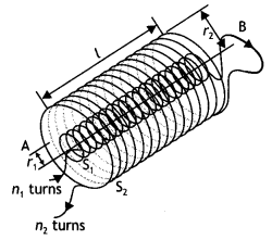
Answer:
(a) The line integral of B around any closed path equals µol, where l is the total steady current passing through any surface bounded by the closed path.” Mathematically
\(\oint \vec{B} \cdot \overrightarrow{d L}=\mu_{0} I\)
(b) (i) The magnetic field due to a current-carrying solenoid:
B = µon l
where n = number of turns per unit length
l = current through the solenoid
Now, the magnetic field due to solenoid S1 will be in the upward direction and the magnetic field due to S2 will be in the downward direction (by right-hand screw rule).

In the upward direction
(ii) The magnetic field is zero outside a solenoid.
Question 12.
Three long straight parallel wires are kept as shown in the Figure. The wire (3) carries a current l
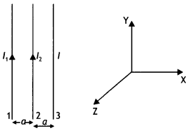
(i) The direction of flow of current l in wire (3) is such that the net force, on a wire (1), due to the other two wires, is zero.
(ii) By reversing the direction of l, the net force on the wire (2), due to the other two wires, becomes zero. What will be the direction of current l, in the two cases? Also obtain the relation between the magnitudes of currents l1, l2, and l. (CBSE Delhi 2016C)
Answer:
Case 1: The direction of flow of current in the wire (3) will be opposite to the direction of flow of current in the wire (1), i.e. downwards.
Also \(\frac{\mu_{0} l_{1} l}{2 \pi(2 a)}=\frac{\mu_{0} l_{1} l_{2}}{2 \pi a}\)
or
l = 2l2
Case 2: The direction of flow of current in wire (3) will be same as the direction of flow of current in wire (1), i.e. upwards. For zero force on wire (2) we have
\(\frac{\mu_{0} l_{1} l_{2}}{2 \pi a}=\frac{\mu_{0} l l_{2}}{2 \pi a}\)
or
l = l1
Therefore l = l1 = 2 l2
Question 13.
Show mathematically that the cyclotron frequency does not depend upon the speed of the particle.
Answer:
Due to the presence of the perpendicular magnetic field the particle moves in a circle of radius r given by
r = \(\frac{m v}{q B}\) ….(1)
The path of the particles in the dees is a semicircle and the time the particle spends in each dees is length of the semi circular path velocity
t = \(\frac{\text { length of the semi circular path }}{\text { velocity }}\)
= \(\frac{\pi r}{v}=\frac{\pi m}{B q}\) …(2)
using equation (1)
The above time is independent of the radius of the path and the velocity of the charged particle. Now the time period of the cyclotron is twice the time spent by the particle in each dee. Thus
T = 2t = \(\frac{2 \pi m}{B q}\) …(3)
Hence cyclotron frequency or the magnetic resonance frequency is given by
v = \(\frac{1}{T}=\frac{B q}{2 \pi m}\) …(4)
which is independent of the speed of the particle.
Question 14.
State the principle of a cyclotron. Show that the time period of revolution of particles in a cyclotron is independent of their speeds. Why is this property necessary for the operation of a cyclotron? (CBSE Al 2016)
Answer:
Principle of cyclotron: It is based on the principle that the positive ions can be accelerated to high energies with a comparatively smaller alternating potential difference by making them cross the electric field again and again, by making use of a strong magnetic field.
The necessary centripetal force required by charged particle to revolve in a circular path in magnetic field is provided by force due to magnetic field, i.e.
\(\frac{m v^{2}}{r}\) = Bqv
or
v = \(\frac{\text { Bqr }}{m}\)
So, the frequency of revolution is then given by
T = \(\frac{2 \pi r}{v}=2 \pi r \times \frac{m}{B q r}=\frac{2 \pi m}{B q}\)
It is clear from the expression that T is Independent of speed.
If this condition is not met the charged particle will very soon go out of step with the applied electricity and will not be accelerated.
Question 15.
(a) Write the expression for the magnetic force acting on a charged particle moving with velocity v in the presence of magnetic field B.
Answer:
\(\vec{F}\) = q\((\vec{v} \times \vec{B})\)
(b) A neutron, an electron and an alpha particle moving with equal velocities enter a uniform magnetic field going into the plane of the paper as shown. Trace their paths in the field and justify your answer. (CBSE Delhi 2016)
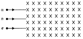
Answer:
The path area is shown.
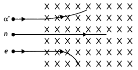
The radius of the circular path traveled by each particle is given by the expression
r = \(\frac{m v}{B q}\) since B and v is the same therefore
we have r ∝ \(\frac{m}{q}\). Since neutron does not have a charge therefore it passes straight without deflection. The ratio m/q for an alpha particle is greater for an alpha particle therefore its path will be less curved.
Also by Fleming’s left-hand rule the alpha particle and the electron will experience a force in the direction as shown.
Question 16.
A long solenoid of length ‘L’ having N turns carries a current l. Deduce the expression for the magnetic field in the interior of the solenoid. (CBSE AI 2011C)
Answer:
Consider a rectangular path abed of length L as shown in the figure below. Let us apply Ampere’s circuital law to this rectangular path so that we have


But by Ampere’s circuital law we have
\(\oint \vec{B} \cdot \vec{d} L\) = μ0Nl = μ0(nL)l …(2)
From equations (1) and (2) we have
BL = μ0nLl
or
B = μ0 n l
But n = N/L, therefore we have
B = μ0 \(\frac{N l}{L}\)
This gives the value of a magnetic field inside a solenoid.
Question 17.
Using Biot-Savart’s law, derive an expression for the magnetic field intensity at the center of a current-carrying circular coil.
Answer:
Consider a circular loop of radius r carrying a current l and having a center at O as shown in the figure below.
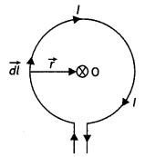
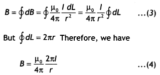
Consider a small current element dL on the loop. Then by Biot-Savart’s law the magnitude of the magnetic field at the center of the loop due to the current element we have
dB = \(\frac{\mu_{0}}{4 \pi} \frac{l d L \sin \theta}{r^{2}}\) …(1)
In this case, the angle between the current element dL and the radius vector is 90° therefore equation (1) can be written as
dB = \(\frac{\mu_{0}}{4 \pi} \frac{l d L}{r^{2}}\) ….(2)
The circular loop can be considered to be consisting of such small elements placed side by side, and then the magnetic intensities of these elements will be in the same direction. Thus, the net intensity of B at the center of the loop is given by
Question 18.
A charged particle q is moving in the presence of a magnetic field B which is inclined to an angle 300 with the direction of the motion of the particle. Draw the trajectory followed by the particle In the presence of the field and explain how the particle describes this path. (CBSE Delhi 2019)
Answer:
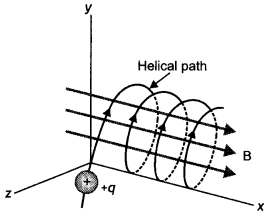
Two components of velocity vector V are responsible for the helical motion. Force on the charged particle due to the component normal to the magnetic field acts perpendicular to the velocity and the magnetic field and makes the particle follow a circular path. The component of velocity which is along the magnetic field does not cause any force on the particle, hence the particle continues to move in a straight line path due to this component so, the resultant path will be helical.
The path is as shown.
Question 19.
Two parallel coaxial circular costs of equal radius ‘R’ and an equal number of turns ‘N’, carry equal currents ‘I’ in the same direction and are separated by a distance ‘2R’. Find the magnitude and direction of the net magnetic field produced at the mid-point of the line joining their centers.
Answer:
The magnetic field at a distance R from a circular coil is given by the expression
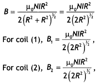
Both are directed in the same direction, therefore the resultant magnetic field at the center is
B = \(\frac{\mu_{0} N l R^{2}}{\left(2 R^{2}\right)^{1 / 2}}\)
Question 20.
(a) State Biot-Savart’s law. Using this law, derive the expression for the magnetic field due to a current-carrying circular loop of radius ‘R’, at a point which is at a distance ‘x’ from Its center along the axis of the loop.
Answer:
It states that for a small current element the small magnetic field is given by the expression Biot-Savart’s law for a small current element \(\overrightarrow{d B}=\frac{\mu_{0}}{4 \pi} \frac{I \overline{(d L} \times \hat{r})}{r^{2}}\).
(b) Two small identical circular loops, marked (1) and (2), carrying equal currents, are placed with the geometrical axes perpendicular to each other as shown in the figure. Find the magnitude and direction of the net magnetic field produced at point O.
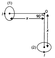
Answer:
The magnetic field at O due to the circular loop 1 is B1 = \(\frac{\mu_{0} l R^{2}}{2\left(x^{2}+R^{2}\right)^{1 / 2}}\) directed towards left.
The magnetic field at O due to the circular loop is B1 = \(\frac{\mu_{0} l R^{2}}{2\left(x^{2}+R^{2}\right)^{1 / 2}}\) directed upwards.
The net magnetic field is therefore
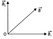
B = \(\sqrt{B_{1}^{2}+B_{2}^{2}}=\sqrt{2} B_{1}=\frac{\mu_{0} l R^{2}}{\sqrt{2}\left(x^{2}+R^{2}\right)^{3 / 2}}\)
The direction of the net magnetic field is 45° with the axis of the loop as shown in the figure below.
Question 21.
Derive an expression for the magnetic field along the axis of an air-cored solenoid, using Ampere’s circuital law. Sketch the magnetic field lines for a finite solenoid. Explain why the field at the exterior mid-point Is weak while at the interior it is uniform and strong.
Answer:
A solenoid is a coil of wire with a Length, which is Large as compared with its diameter.
Consider an ideaL soLenoid carrying current l and having n turns per unit length.
(a) Consider a rectangular path abed of length L as shown in the figure below. Let us apply Ampere’s circuital law to this rectangular path so that we have


But by Ampere’s circuital law we have
\(\oint \vec{B} \cdot \vec{d} L\) = μ0Nl = μ0(nL)l …(2)
From equations (1) and (2) we have
BL = μ0nLl
or
B = μ0 n l
But n = N/L, therefore we have
B = μ0 \(\frac{N l}{L}\)
This gives the value of a magnetic field inside a solenoid.
(b) The sketch Is as shown below.
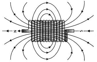
The magnetic field gets added inside the solenoid whereas it is not added outside the solenoid.
Question 22.
(a)Using Ampere’s circuital law, obtain the expression for the magnetic field due to a long solenoid at a point inside the solenoid on its axis.
Answer:
Consider a rectangular path abed of length L as shown in the figure below. Let us apply Ampere’s circuital law to this rectangular path so that we have


But by Ampere’s circuital law we have
\(\oint \vec{B} \cdot \vec{d} L\) = μ0Nl = μ0(nL)l …(2)
From equations (1) and (2) we have
BL = μ0nLl
or
B = μ0 n l
But n = N/L, therefore we have
B = μ0 \(\frac{N l}{L}\)
This gives the value of a magnetic field inside a solenoid.
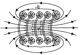
(b) In what respect is a toroid different from a solenoid? Draw and compare the pattern of the magnetic field lines in the two cases.
Answer:
(b) In a toroid magnetic field is uniform whereas in a solenoid it is different at the two ends and the center.
The magnetic field lines around the two are as shown.
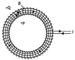
(c) How is the magnetic field inside a given solenoid made strong? (CBSE Al 2011)
Answer:
(i) By inserting a ferromagnetic substance inside the solenoid.
(ii) By increasing the amount of current through the solenoid.
Question 23.
(a) Explain, giving reasons, the basic difference in converting a galvanometer into
(i) a voltmeter
Answer:
A voltmeter is always connected in parallel with the section of the circuit whose potential difference has to be measured. Further, it must draw a small current, otherwise, the voltage measurement will disturb the original setup by an amount that is very large. Thus a large resistance is connected to the galvanometer in series so as to minimize this effect.
(ii) an ammeter
Answer:
An ammeter measures current and is to be connected in series in a circuit. A galvanometer has a large resistance, therefore a shunt is connected to it in order to decrease its resistance such that the current in the circuit is not altered.
(b) Two long straight parallel conductors carrying steady currents l1 and l2 are separated by a distanced’. Explain briefly, with the help of a suitable diagram, how the magnetic field due to one conductor acts on the other. Hence deduce the expression for the force acting between the two conductors. Mention the nature of this force. (CBSE At 2012)
Answer:
Consider two long, straight parallel wires separated by a distance ‘a’ and carrying currents l1 and l2 in the same direction as shown. We can easily determine the force on one wire due to the magnetic field set-up by the other wire. Wire 2, which carries a current l2, sets up a magnetic field B2 at the position of wire 1.
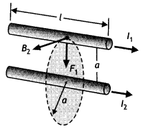
The direction of B2 is perpendicular to the wire, as shown in figure. Now the magnetic force on length L of wire 1 is
\(\vec{F}_{1}=l_{1}\left(\vec{L} \times \vec{B}_{2}\right)\)
Since L is perpendicular to B2, the magnitude of F, is given by F1 = l1 L B2 …(1)
But the field due to wire 2 is given by the relation
B2 = \(\frac{\mu_{0} l_{2}}{2 \pi a}\) ….(2)
Therefore, from equations 1 and 2 we have
F1= l1 L B2 = l1 L\(\left(\frac{\mu_{0} l_{2}}{2 \pi a}\right)=\frac{L \mu_{0} l_{1} l_{2}}{2 \pi a}\)
We can rewrite it in terms of force per unit length as
\(\frac{F_{1}}{L}=\frac{\mu_{0} l_{1} l_{2}}{2 \pi a}\) ….(3)
The direction of F1 is downward, towards wire 2, since \(\vec{L} \times \vec{B}\) is downwards. If one considers the field set up at wire 2 due to wire 1, the force F2 is found to be equal and opposite to F1 which is in accordance with Newton’s third law of motion. When the currents are in opposite directions, the forces are reversed and the wires repel each other. Hence we find that the force per unit length of wire between two parallel current-carrying wires is given by
F = \(\frac{\mu_{0} l_{1} l_{2}}{2 \pi a}\)
Therefore, two conductors carrying current in the same direction attract each other whereas two conductors carrying current in the opposite directions repel each other.
The above expression can be used to define ampere, the SI unit of current.
Let l1 = l2 = 1 ampere, a = 1 m then F = 2 × 10⁻⁷ Nm-1
Thus we have
One ampere is that much current which when flowing through each of the two infinitely long straight conductors held 1 meter apart in space, produce a force of F = 2 × 10⁻⁷ N per meter of their length.
Question 24.
(a) State the underlying principle of a moving coil galvanometer.
Answer:
A current-carrying coil placed in a magnetic field experiences a torque.
(b) Give two reasons to explain why a galvanometer cannot as such be used to measure the value of the current in a given circuit.
Answer:
- A galvanometer is a very sensitive device; it gives a full-scale deflection for a current of the order of a few pA.
- The resistance of the galvanometer is not very small, hence it will change the value of current in the circuit branch when connected in series in that branch.
(c) Define the terms:
(i) voltage sensitivity and
(ii) current sensitivity of a galvanometer. (CBSE Delhi 2019)
Answer:
- Voltage sensitivity: Voltage sensitivity is defined as the deflection per unit potential difference applied.
- Current sensitivity: It is defined as the deflection per unit current.
Question 25.
(a) State Biot-Savart law. Deduce the expression for the magnetic field due to a circular current carrying loop at a point lying on its axis.
Answer:
It states that for a small current element the small magnetic field is given by the expression Biot-Savart’s law for a small current element \(\overrightarrow{d B}=\frac{\mu_{0}}{4 \pi} \frac{I \overline{(d L} \times \hat{r})}{r^{2}}\).
(b) Two long parallel wires carry currents l1 and l1 flowing in the same direction. When a third current-carrying wire is placed parallel and coplanar in between the two, find the condition when the third wire would experience no force due to these two wires. (CBSE AI 2012C)
Answer:
Two current-carrying wires carrying current in the same direction attract and those carrying current in the opposite direction repel. The current in the third wire at the center should be opposite to the current in the two wires.
The conditions should be
- The center wire should carry current in the opposite direction to the two wires and
- The center wire should be closer to the wire carrying lesser current.
Question 26.
(a) Derive the expression for the torque on a rectangular current-carrying loop suspended in a uniform magnetic field.
Answer:
The figure below shows a rectangular loop of wire with length ‘a’ and breadth ‘b’. A line perpendicular to the plane of the loop (i.e. a normal to the plane) makes an angle Φ with the direction of the magnetic field B, and the loop carries a current / as shown. Let the forces acting on the various sides of the loop be \(\vec{F}_{1}\), \(\vec{F}_{2}\), \(\vec{F}_{3}\) and \(\vec{F}_{4}\) as shown.
It follows from the expression for the force experienced by a conductor in a magnetic field that force on arm AB is
\(\vec{F}_{1}=I(\overrightarrow{\mathrm{AB}} \times \vec{B})\) …(1)
(in the plane of the paper and is directed upwards as shown).
The force on arm CD is given by \(\vec{F}_{2}=l(\overrightarrow{\mathrm{CD}} \times \vec{B})\) …(2)
(in the plane of the paper and is directed downwards as shown.)
Since these two forces are equal and opposite and have the same line of action therefore they cancel out each other’s effect and their resultant effect on the coil is zero.
Now the force on arm BC is
\(\vec{F}_{3}=l(\overrightarrow{\mathrm{BC}} \times \vec{B})\) …(3)
(acts perpendicular to the plane of the paper and is directed outwards as shown) Finally the force on arm DA is
\(\vec{F}_{4}=I(\overrightarrow{\mathrm{DA}} \times \vec{B})\) …(4)
(acts perpendicular to the plane of the paper and is directed inwards as shown in figure).
Both forces F<sub>3</sub> and F4 make an angle of 90° with the direction of the magnetic field. Therefore, in magnitude, these forces are given by
F3 = F4 = l a B sin90° = l a B …(5)
The lines of action of both these forces are perpendicular to the plane of the paper. The two forces F3 and F4 lie along different lines and each give rise to a torque about the X-axis. The two torques produce a resultant torque in the + X direction. The arm of the couple (perpendicular distance between the lines of action of the two forces) from the figure below is given by
The arm of couple = b Sin Φ …(6)
Therefore, by the definition of torque we have
Torque = either force × arm of couple Using equations (5) and (6) we have
Torque = l B a × b Sin Φ
But a b = A, area of the coil, therefore τ = l B A Sin Φ

(b) A proton and a deuteron having equal momenta enter in a region of the uniform magnetic field at a right angle to the direction of the field. Depict their trajectories in the field. (CBSE Delhi 2013)
Answer:
The radius of the curved path which will be followed by the two particles is given by the expression r = \(\frac{m v}{B q}\)
As md > mp it will follow the path of a bigger radius.
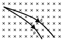
Question 27.
State Biot-Savart law, expressing it in the vector form. Use it to obtain the expression for the magnetic field at an axial point, distance ‘d’ from the center of a circular coil of radius ‘a’ carrying current ‘l’. Also, find the ratio of the magnitudes of the magnetic field of this coil at the center and at an axial point for which d = a \(\sqrt{3}\) (CBSE Delhi 2013C)
Answer:
(a) It states that the magnetic field due to a current element dl at a distance r from it is given by the expression
dB = \(\frac{\mu_{0}}{4 \pi} \frac{l d l \sin \theta}{r^{2}}\). In vector form it is written as
\(\overrightarrow{d B}=k_{m} \frac{l mid \overrightarrow{d L} \times \hat{r}}{r^{2}}\)
Consider a circular loop of wire of radius R located in the YZ plane and carrying a steady current / as shown in the figure below. Let us calculate the magnetic field at an axial point P a distance x from the center of the loop. From the figure it is clear that any element dL is perpendicular to r, furthermore, all the elements around the loop are at the same distance r from P, where r2 = X2 + R2. Hence by Biot-Savart’s law, the magnetic field at point P due to the current element dL is given by

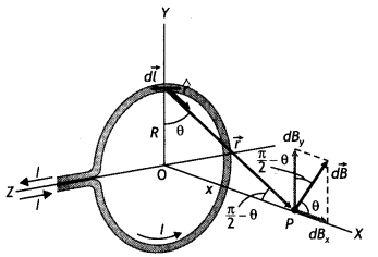
The direction of the magnetic field dB due to the eLement dL is perpendicular to the plane formed by r and dL as shown in the figure above. The vector dB can be resolved into components dB aLong the X-axis and dB which is perpendicular to the X-axis. When the components perpendicular to the X-axis are assumed over the whole loop, the result is zero. That is, by symmetry any element on one side of the loop will set up a perpendicular component that cancels the component setup by an element diametrically opposite it. Therefore, it is obvious that the resultant magnetic field at P will be along the X-axis. This result can be obtained by integrating the components dBx = dB cos θ.
Therefore, we have

where the integral is to be taken over the entire loop since θ,x and R are constants for all elements of the loop and since
cos θ = \(\frac{R}{\sqrt{x^{2}+R^{2}}}\)
B = \(\frac{\mu_{0} l R}{4 \pi\left(x^{2}+R^{2}\right)^{3 / 2}} \oint d L=\frac{\mu_{0} l R^{2}}{2\left(x^{2}+R^{2}\right)^{1 / 2}}\)
To find the magnetic field at the centre of the loop setting x = O in equation the above equation we have B = \(\frac{\mu_{0} l}{2 R}\)
Now magnetic field at the centre of a circular coil is
\(B_{C}=\frac{\mu_{0} l}{2 a}\) …(1)
Also magnetic field on the axial line when
d = a\(\sqrt{3}\) is

From (1) and (2) we have
\(\frac{B_{C}}{B_{\text {axial }}}=\frac{\mu_{0} l}{2 a} \times \frac{16 a}{\mu_{0} l}\) = 8
Question 28.
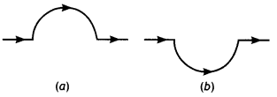
A straight wire carrying a current of 12 A is bent into a semi-circular arc of radius 2.0 cm as shown in figure (a) Consider the magnetic field B at the center of the arc
(a) What is the magnetic field due to the straight segments?
(b) In what way the contribution to B from the semicircle differs from that of a circular loop and in what way does it resemble?
(c) Would your answer be different if the wire were bent into a semi-circular arc of the same radius but in the opposite way as shown in figure (b)? (NCERT)
Answer:
(a) dl and r for each element of the straight segments are parallel. Therefore \(d \vec{L} \times \hat{r}\) =0. Straight segments do not contribute to the magnetic field at the center of the semicircular arc.
(b) For all segments of the semicircular arc \(d \vec{L} \times \hat{r}\) are all parallel to, each other (into the plane of the paper). All such contributions add up in magnitude. Hence the direction of B for a semicircular arc is given by the right-hand rule and magnitude is half that of a circular loop. Thus
B = \(\frac{1}{2} \frac{\mu_{0} l}{2 r}=\frac{4 \pi \times 10^{-7} \times 12}{4 \times 2 \times 10^{-2}}\) = 9 × 10⁻⁴ T normal to the plane of the paper going into it.
(c) Same magnitude of B but opposite in direction to that in (b)
Question 29.
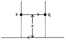
A long straight wire carrying a current of 25 A rests on a table as shown in the figure. Another wire PQ of length 1 m, mass 2.5 g carries the same current but in the opposite direction. The wire PQ is free to slide up and down. To what height will PQ rise? (NCERT Exemplar)
Answer:
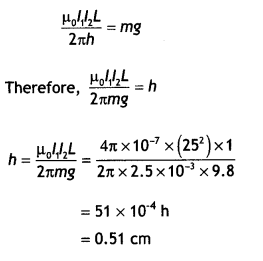
Given l1 = l1 = 25 A, L = 1 m, m = 2.5 g = 2.5 × 10⁻³ kg
The repulsive force between PQ and the wire on the table will balance the weight of wire PQ. Let this happen when PQ is at a height h above the wire, then
F = mg
Question 30.
Two straight parallel conductors carry steady currents l1 and l2 separated by a distance d. if currents are flowing in the same direction, show how the magnetic field set-up in one produces an attractive force on the other. Obtain the expression for force. Hence define one ampere. (CBSE Delhi 2016)
Answer:
Consider two long, straight parallel wires separated by a distance ‘a’ and carrying currents l1 and l2 in the same direction as shown. We can easily determine the force on one wire due to the magnetic field set-up by the other wire. Wire 2, which carries a current l2, sets up a magnetic field B2 at the position of wire 1.

The direction of B2 is perpendicular to the wire, as shown in figure. Now the magnetic force on length L of wire 1 is
\(\vec{F}_{1}=l_{1}\left(\vec{L} \times \vec{B}_{2}\right)\)
Since L is perpendicular to B2, the magnitude of F, is given by F1 = l1 L B2 …(1)
But the field due to wire 2 is given by the relation
B2 = \(\frac{\mu_{0} l_{2}}{2 \pi a}\) ….(2)
Therefore, from equations 1 and 2 we have
F1= l1 L B2 = l1 L\(\left(\frac{\mu_{0} l_{2}}{2 \pi a}\right)=\frac{L \mu_{0} l_{1} l_{2}}{2 \pi a}\)
We can rewrite it in terms of force per unit length as
\(\frac{F_{1}}{L}=\frac{\mu_{0} l_{1} l_{2}}{2 \pi a}\) ….(3)
The direction of F1 is downward, towards wire 2, since \(\vec{L} \times \vec{B}\) is downwards. If one considers the field set up at wire 2 due to wire 1, the force F2 is found to be equal and opposite to F1 which is in accordance with Newton’s third law of motion. When the currents are in opposite directions, the forces are reversed and the wires repel each other. Hence we find that the force per unit length of wire between two parallel current-carrying wires is given by
F = \(\frac{\mu_{0} l_{1} l_{2}}{2 \pi a}\)
Therefore, two conductors carrying current in the same direction attract each other whereas two conductors carrying current in the opposite directions repel each other.
The above expression can be used to define ampere, the SI unit of current.
Let l1 = l2 = 1 ampere, a = 1 m then F = 2 × 10⁻⁷ Nm-1
Thus we have
One ampere is that much current which when flowing through each of the two infinitely long straight conductors held 1 meter apart in space, produce a force of F = 2 × 10⁻⁷ N per meter of their length.
Question 31.
(a) In a moving coil galvanometer, why is the magnetic field required to be radial?
Answer:
The radial field is always normal to the surface of the coil in all positions of the coil, i.e. θ = 0. The radial field ensures a linear relation between 0 and l in a moving coil galvanometer.
(b) A 100 turn closely wound circular coil of radius 10 cm carries a current of 3.2 A.
Calculate (i) the magnetic field at the centre of the coil, and
(ii) its magnetic moment. (CBSE2019C)
Answer:
Here N = 100, r = 10 cm = 0.1 m,
l = 3.2 A, B = ?, p = ?
(i) At the centre of the coil

(ii)Magnetic moment
p = NIA
= 100 × 3.2 × π × (0.1 )2 ≃ 10 Am2
Question 32.
State Ampere’s circuital law. Use this law to find a magnetic field due to a straight infinite current-carrying wire. How are the magnetic field lines different from the electrostatic field lines? (CBSE Al 2016)
Answer:
Statement: “The line integral of B around any closed path equals μ0 l, where l is the total steady current passing through any surface bounded by the closed path.”
Consider a long circular wire of radius ‘a’ carrying a steady current (dc) that is uniformly distributed along the cross-section of the wire as shown in the figure. Let us calculate the magnetic field in the regions r ≥ a and r < a. In region 1 let us choose a circular path of radius r centered at the wire. From symmetry, we find that B is perpendicular to dL at every point on the circular path.
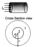
Since total current linked with the circular path is l0, therefore by Ampere’s law we have

for r ≥ a
Magnetic field lines form closed loops while electrostatics field lines do not.
Question 33.
(a) State Biot-Savart law in vector form.
Answer:
It states that for a small current element the small magnetic field is given by the expression Biot-Savart’s law for a small current element \(\overrightarrow{d B}=\frac{\mu_{0}}{4 \pi} \frac{I \overline{(d L} \times \hat{r})}{r^{2}}\).
(b) Deduce the expression for the magnetic field at a point on the axis of a current-carrying circular loop of radius ‘R’, distant V from the center, hence write the magnetic field at the center of a loop. (CBSE AI 2015, Delhi 2018C)
Answer:
Consider a circular loop of wire of radius R located in the YZ plane and carrying a steady current / as shown in the figure below. Let us calculate the magnetic field at an axial point P a distance x from the center of the loop. From the figure it is clear that any element dL is perpendicular to r, furthermore, all the elements around the loop are at the same distance r from P, where r2 = X2 + R2. Hence by Biot-Savart’s law, the magnetic field at point P due to the current element dL is given by


The direction of the magnetic field dB due to the element dL is perpendicular to the plane formed by r and dL as shown in the figure above. The vector dB can be resolved into components dB along the X-axis and dB which is perpendicular to the X-axis. When the components perpendicular to the X-axis are assumed over the whole loop, the result is zero. That is, by symmetry any element on one side of the loop will set up a perpendicular component that cancels the component setup by an element diametrically opposite it. Therefore, it is obvious that the resultant magnetic field at P will be along the X-axis. This result can be obtained by integrating the components dBx = dB cos θ.
Therefore, we have

where the integral is to be taken over the entire loop since θ,x and R are constants for all elements of the loop and since
cos θ = \(\frac{R}{\sqrt{x^{2}+R^{2}}}\)
B = \(\frac{\mu_{0} l R}{4 \pi\left(x^{2}+R^{2}\right)^{3 / 2}} \oint d L=\frac{\mu_{0} l R^{2}}{2\left(x^{2}+R^{2}\right)^{1 / 2}}\)
To find the magnetic field at the centre of the loop setting x = O in equation the above equation we have B = \(\frac{\mu_{0} l}{2 R}\)
Question 34.
Derive an expression for the maximum force experienced by a straight conductor of length 1, carrying current I and kept in a uniform magnetic field, B.
Answer:
Consider a straight segment of a conducting wire; with length L and cross-section at area A, the current is from bottom to top as shown In the figure below. The wire is in a uniform magnetic field B perpendicular to the plane of the diagram and directed into the plane. Let us assume that the moving charges are positive.
The drift velocity is upward, perpendicular to B. The average force experienced by each charge is
\(\vec{f}=q\left(\vec{v}_{d} \times \vec{B}\right)\) …..(1)
Directed to the left as shown in the figure
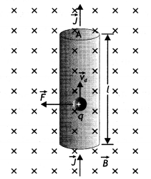
Since \(\vec{V}_{d}\) and \(\vec{B}\) are perpendicular, the magnitude of the force is given by
f = q vd B …(2)
Let n be the number density of charges, i.e. number of charges per unit volume. A segment of the conductor with length L has volume V = A L and contains a number of charges N given by
N = n A L …(3)
Now the total force F on all the charges moving in this segment is
F = N f = (n A L) q vd B = (n q vd A) (L B)
But n q vd A = l, therefore the above equation becomes
F = B l L …(4)
Question 35.
Derive an expression for the torque on a rectangular coil of area A, carrying a current l and placed in a magnetic field B, the angle between the direction of 8 and the vector perpendicular to the plane of the coil is θ. (CBSE Delhi 2019)
Answer:
The figure below shows a rectangular loop of wire with length ‘a’ and breadth ‘b’. A line perpendicular to the plane of the loop (i.e. a normal to the plane) makes an angle Φ with the direction of the magnetic field B, and the loop carries a current / as shown. Let the forces acting on the various sides of the loop be \(\vec{F}_{1}\), \(\vec{F}_{2}\), \(\vec{F}_{3}\) and \(\vec{F}_{4}\) as shown.
It follows from the expression for the force experienced by a conductor in a magnetic field that force on arm AB is
\(\vec{F}_{1}=I(\overrightarrow{\mathrm{AB}} \times \vec{B})\) …(1)
(in the plane of the paper and is directed upwards as shown).
The force on arm CD is given by \(\vec{F}_{2}=l(\overrightarrow{\mathrm{CD}} \times \vec{B})\) …(2)
(in the plane of the paper and is directed downwards as shown.)
Since these two forces are equal and opposite and have the same line of action therefore they cancel out each other’s effect and their resultant effect on the coil is zero.
Now the force on arm BC is
\(\vec{F}_{3}=l(\overrightarrow{\mathrm{BC}} \times \vec{B})\) …(3)
(acts perpendicular to the plane of the paper and is directed outwards as shown) Finally the force on arm DA is
\(\vec{F}_{4}=I(\overrightarrow{\mathrm{DA}} \times \vec{B})\) …(4)
(acts perpendicular to the plane of the paper and is directed inwards as shown in figure).
Both forces F3 and F4 make an angle of 90° with the direction of the magnetic field. Therefore, in magnitude, these forces are given by
F3 = F4 = l a B sin90° = l a B …(5)
The lines of action of both these forces are perpendicular to the plane of the paper. The two forces F3 and F4 lie along different lines and each give rise to a torque about the X-axis. The two torques produce a resultant torque in the + X direction. The arm of the couple (perpendicular distance between the lines of action of the two forces) from the figure below is given by
The arm of couple = b Sin Φ …(6)
Therefore, by the definition of torque we have
Torque = either force × arm of couple Using equations (5) and (6) we have
Torque = l B a × b Sin Φ
But a b = A, area of the coil, therefore τ = l B A Sin Φ

Question 36.
Draw a schematic sketch of a cyclotron. State its working principle and write its two uses. (CBSE 2019C)
Answer:
Cyclotron
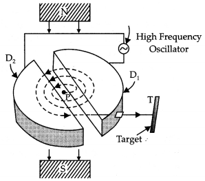
Working Principle: It is based on the principle that a positively charged particle can acquire very large energy with the small alternating potential difference if the particle is made to cross again and again the electric field produced by alternating potential difference applied and a strong perpendicular magnetic field is applied.
Uses:
(a) It is used to accelerate positively charged particles to very high energies.
(b) Cyclotrons are a source of high-energy beams for nuclear physics experiments.
Question 37.
(a) Draw a schematic sketch of a moving coil galvanometer and describe briefly its working.
Answer:
Principle: It is based on the principle that the positive ions can be accelerated to high energies with a comparatively smaller alternating potential difference by making them cross the electric field again and again, by making use of a strong magnetic field.
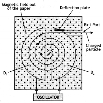
Construction: It consists of two D-shaped, hollow metal dees D1 and D2. The dees are placed with a small gap in between them. The dees are connected to a source of high frequency alternating potential difference. The dees are evacuated in order to minimize energy losses resulting from collisions between the ions and air molecules. The whole apparatus is placed between the poles of an electromagnet as shown in the figure below. The magnetic field is perpendicular to the plane of the dees.
Working: In a cyclotron, particles of mass m and charge q move inside an evacuated chamber in a uniform magnetic field B that is perpendicular to the plane of their paths. The alternating potential difference applied between the hollow electrodes D1 and D2 create an electric field in the gap between them which changes precisely twice in each revolution so that the particles get a push each time they cross the gap.
The pushes increase their speed and kinetic energy, boosting them into paths of larger radius. The electric field increases the speed and the magnetic field makes the particles move in circular paths. Due to the presence of the perpendicular magnetic field the particle moves in a circle of radius r given by
r = \(\frac{m v}{q B}\) …(1)
The path of the particles in the dees is a semicircle and the time the particle spends in each dee is semi-circular
τ = \(\frac{\text { length of the semi-circular path }}{\text { velocity }}=\frac{\pi r}{v}=\frac{\pi m}{B q}\) by using equation (1)
The above time is independent of the radius of the path and the velocity of the charged particle. Hence the charged particle spends the same time in each dee and encounters a dee of opposite polarity whenever it comes into the gap between the dees and thus is continuously accelerated.
(b) “Increasing the current sensitivity of a galvanometer does not necessarily increase the voltage sensitivity.” Justify’ this statement. (CBSE Delhi 2014C)
Answer:
Voltage and current sensitivities are related as VS = \(\frac{CS}{R}\) .
An increase in current sensitivity may lead to an increase in the resistance of the coil. Thus the factor CS/R may not be affected.
Question 38.
Explain with the help of a labeled diagram the underlying principle, construction, and working of a moving coil galvanometer.
Answer:
It is an instrument used to detect weak currents in a circuit.
Principle: It is based on the principle that, whenever a loop carrying current is placed in a magnetic field, it experiences a torque, which tends to rotate it.
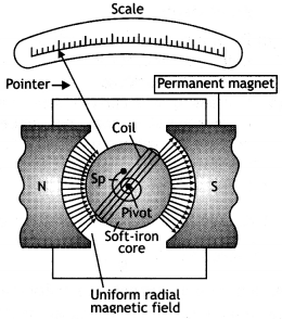
Construction: It consists of a rectangular or circular coil made by winding a fine insulated copper wire on an aluminum frame. A thin phosphor bronze strip from a torsion head, which is connected to a terminal screw, suspends this coil. The lower end of the coil is connected to a fine spring which is connected to another terminal screw. The coil hangs in space between the pole pieces of a powerful horseshoe magnet NS as shown in the figure below. The pole pieces are made concave cylindrical.
This provides a radial magnetic field. Since the field is radial, therefore the plane of the coil remains parallel to the magnetic field in all the orientations of the coil. In between the pole pieces, within the coil, lies a soft iron cylindrical piece called ‘core’. The core does not touch the coil anywhere. The whole arrangement is enclosed in a non-magnetic box to protect it from air currents. Three leveling screws are provided at the base.
Question 39.
Explain with the help of a labeled diagram the underlying principle, construction, and working of a cyclotron. (CBSE Delhi 2019)
Answer:
Principle: It is based on the principle that the positive ions can be accelerated to high energies with a comparatively smaller alternating potential difference by making them cross the electric field again and again, by making use of a strong magnetic field.

Construction: It consists of two D-shaped, hollow metal dees D1 and D2. The dees are placed with a small gap in between them. The dees are connected to a source of high frequency alternating potential difference. The dees are evacuated in order to minimize energy losses resulting from collisions between the ions and air molecules. The whole apparatus is placed between the poles of an electromagnet as shown in the figure below. The magnetic field is perpendicular to the plane of the dees.
Working: In a cyclotron, particles of mass m and charge q move inside an evacuated chamber in a uniform magnetic field B that is perpendicular to the plane of their paths. The alternating potential difference applied between the hollow electrodes D1 and D2 create an electric field in the gap between them which changes precisely twice in each revolution so that the particles get a push each time they cross the gap. The pushes increase their speed and kinetic energy, boosting them into paths of larger radius. The electric field increases the speed and the magnetic field makes the particles move in circular paths. Due to the presence of the perpendicular magnetic field the particle moves in a circle of radius r given by
r = \(\frac{m v}{q B}\) …(1)
The path of the particles in the dees is a semicircle and the time the particle spends in each dee is semi-circular
τ = \(\frac{\text { length of the semi-circular path }}{\text { velocity }}=\frac{\pi r}{v}=\frac{\pi m}{B q}\) by using equation (1)
The above time is independent of the radius of the path and the velocity of the charged particle. Hence the charged particle spends the same time in each dee and encounters a dee of opposite polarity whenever it comes into the gap between the dees and thus is continuously accelerated.
Question 40.
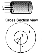
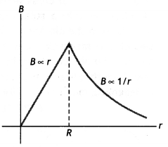
The figure below shows a long straight wire of circular cross-section (radius a) carrying steady current l. The current is uniformly distributed across this cross-section. Calculate the magnetic field in the region r < a and r > a. Draw a graph showing the variation of a magnetic field for the above two cases.
Answer:
Consider a long circular wire of radius ‘a’ carrying a steady current (dc) that is uniformly distributed along the cross-section of the wire as shown in the figure. Let us calculate the magnetic field in the regions r ≥ a and r < a. In region 1 let us choose a circular path of radius r centered at the wire. From symmetry, we find that B is perpendicular to dL at every point on the circular path. Since total current linked with the circular path 1 is l0, therefore by Ampere’s law we have

for r ≥ a
Now consider the interior of the wire, i.e. region 2 where r < a. In this, the current l enclosed by the path is less than l<sub>0</sub>. Since the current is assumed to be uniform over the area of the wire,
Therefore

Now applying Ampere’s circuital rule to region 2 we have
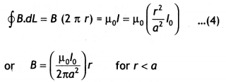
The magnetic field versus r for this system is as shown in the figure below.
Question 41.
Draw the magnetic field lines due to a circular loop of area \(\vec{A}\) carrying current I. Show that it acts as a bar magnet of magnetic moment \(\vec{m}=I \vec{A}\). (CBSE Al 2015)
Answer:
The magnetic field lines are as shown
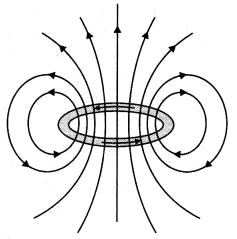
Magnetic field due to circular loop on its axis at far off points
B = \(\frac{\mu_{0}}{4 \pi} \frac{2 I A}{X^{3}}\)
Magnetic field due to a bar magnet at its axial point is
B = \(\frac{\mu_{0}}{4 \pi} \frac{2 m}{x^{3}}\)
Comparing the above two we have m = IA
Question 42.
(a) State Ampere’s circuital law. Use this law to obtain the expression for the magnetic field inside an air-cored toroid of average radius ‘r, having ‘n’ turns per unit length and carrying a steady current.
(b) An observer to the left of a solenoid of N turns each of cross-section area ‘A’ observes that a steady current I in it flows in the clockwise direction. Depict the magnetic field lines due to the solenoid specifying its polarity and show that it acts as a bar magnet of magnetic moment m = NIA. (CBSE Delhi 2015)

Answer:
(a) “The line integral of 8 around any closed path equal μ0l, where l is the total steady current passing through any surface bounded by the closed path.” Consider a toroidal solenoid. Let N be the number of turns and l be the current passed through it. For a solenoid whose coils are closely spaced, the field inside the solenoid is tangent to the dotted circular path as shown in the figure and is the same at all points lying on the dotted line.
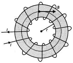
Therefore we have
\(\oint \vec{B} \cdot d \vec{L}\) = B ∮dL = B (2 π r) …(1)
By Ampere’s circuital law we have ∮\(\overrightarrow{\mathbf{B}} \cdot d \vec{L}\) = μ0Nl …(2)
From equations 1 and 2 we have
B (2 π r) = μ0NI
or
B = \(\frac{\mu_{0} N I}{2 \pi r}\) but
\(\frac{N}{2 \pi r}\) = n
i. e. number of turns per unit length Therefore we have B = μ0 n I
This gives the field inside a toroidal solenoid.
(b) The magnetic field lines and the polarity of the solenoid is as shown.

Magnetic field due to the coil on its axis at far off points
B = \(\frac{\mu_{0}}{4 \pi} \frac{2 N I A}{x^{3}}\)
Magnetic field due to a bar magnet at its axial point is
B = \(\frac{\mu_{0}}{4 \pi} \frac{2 m}{x^{3}}\)
Comparing the above two we have m = NIA
Question 43.
(a) Use Biot-Savart law to derive the expression for the magnetic field due to a circular coil of radius R having N turns at a point on the axis at a distance ‘x’ from its center.
Draw the magnetic field lines due to this coil.
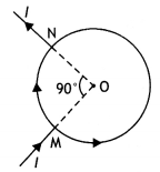
(b) A current l enters a uniform loop of radius R at point M and flows out at point N as shown in the figure. Obtain the net magnetic field at the center of the loop. (CBSE Delhi 2015C)
Answer:
(a) According to Biot-Savart law:
The magnitude of magnetic field d \(\vec{B}\) , is due to a current element d \(\vec{l}\), is proportional to current l and element length, dl.
inversely proportional to the square of the distance r.
Its direction is perpendicular to the plane containing d \(\vec{l}\) and \(\vec{r}\) .
In vector notation,
\(\overrightarrow{d B}=\frac{\mu_{0}}{4 \pi}, \frac{d \vec{l} \times \vec{r}}{r^{3}}\)
Using Biot-Savart law, obtain the expression for the magnetic field due to a circular coil of radius r, carrying a current I at a point on its axis distant x from the centre of the coil. (CBSE Delhi 2018C)
Answer:
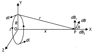
we have \(\overrightarrow{d B}=\frac{\mu_{0}}{4 \pi} I \frac{|d \vec{i} \times \vec{r}|}{r^{3}}\)
r² = x² + R²
∴ dB = \(\frac{\mu_{0} I}{4 \pi} \frac{d l}{\left(X^{2}+R^{2}\right)^{3 / 2}}\)
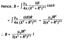
The magnetic fieLd Lines are as shown.
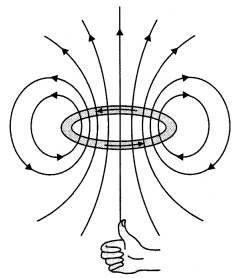
(b) At point O, the net magnetic field is the sum of fields due to two current segments carrying currents /1 and l2. If the potential difference between points A and B be V, then
V = I1 R1 = I2R2
where R, is the resistance of segment subtending an angle 90° at O and R2 is the resistance of segment subtending an angle (360° – 90°) at O.
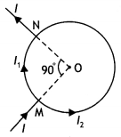
Now R1 = \(\frac{\pi / 2}{2 \pi} R=\frac{R}{4}\)
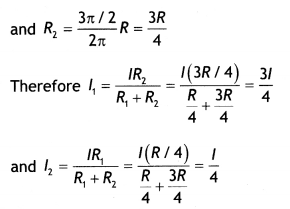
Now field B1, at O due to smaller segment is

directed inwards.
Now field B2 at 0 due to larger segment is

directed outwards
Hence net magnetic field in the center is
B1 – B2 = \(\frac{3 \mu_{0} I}{32 r}-\frac{3 \mu_{0} I}{32 r}\) = 0
(ii) The velocity of the particle inside a cyclotron is given by v = \(\frac{B q r}{m}\) , which again depends upon the q/m ratio. The q/m ratio of an a particle is less than that of a proton, therefore a proton will come out with higher velocity.
Question 44.
(a) Define the SI unit of current in terms of the force between two parallel current-carrying conductors.
(b) Two long straight parallel conductors carrying steady currents la and lb along the same direction are separated by a distance d. How does one explain the force of attraction between them? If a third conductor carrying a current lc in the opposite direction is placed just in the middle of these conductors, find the resultant force acting on the third conductor. (CBSE Delhi 2018C)
Answer:
(a) The ampere is the value of that steady current which, when maintained in each of the two very long, straight, parallel conductors of negligible cross¬section, and placed one meter apart in vacuum, would produce on each of these conductors a force equal to 2 × 10⁻⁷ newton per meter of length.
(b) The wire (ii) experiences a force due to the magnetic field caused by the current flowing in wire (i).
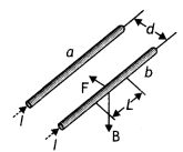
The magnetic field at any point on the wire (b) due to the current in the wire (a) is perpendicular to the plane of two wires and pointing inwards and hence force on it will be towards wire (a). Similarly, the force on the wire (a) will be towards wire (b). Hence two wires carrying currents in the same direction attract each other.
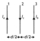
Force on wire (3) due to wire (1)
\(\frac{\mu_{0} l_{a} l_{c}}{2 \pi\left(\frac{d}{2}\right)}\) towards right
Force on wire 3 due to wire 2
\(\frac{\mu_{0} l_{b} l_{c}}{2 \pi\left(\frac{d}{2}\right)}\) towards Left
Net force on wire 3
\(\frac{\mu_{0} I_{c}}{\pi d}\left[I_{a}-I_{b}\right]\) towards right nd °
Also accept
\(\frac{\mu_{0} I_{c}}{\pi d}\left[I_{b}-I_{a}\right]\) towards left
Question 45.
(a) State Biot-Savart law and express it in the vector form.
Answer:
(a) According to Biot-Savart law:
The magnitude of magnetic field d \(\vec{B}\) , is due to a current element d \(\vec{l}\), is proportional to current l and element length, dl.
inversely proportional to the square of the distance r.
Its direction is perpendicular to the plane containing d \(\vec{l}\) and \(\vec{r}\) .
In vector notation,
\(\overrightarrow{d B}=\frac{\mu_{0}}{4 \pi}, \frac{d \vec{l} \times \vec{r}}{r^{3}}\)
(b) Using Biot-Savart law, obtain the expression for the magnetic field due to a circular coil of radius r, carrying a current I at a point on its axis distant x from the centre of the coil. (CBSE Delhi 2018C)
Answer:

we have \(\overrightarrow{d B}=\frac{\mu_{0}}{4 \pi} I \frac{|d \vec{i} \times \vec{r}|}{r^{3}}\)
r² = x² + R²
∴ dB = \(\frac{\mu_{0} I}{4 \pi} \frac{d l}{\left(X^{2}+R^{2}\right)^{3 / 2}}\)

Question 46.
Derive an expression for the velocity y0 of a positive ion passing undeflected through a region where crossed uniform electric field E and magnetic field B are simultaneously present. Draw and justify the trajectory of identical positive ions whose velocity has a magnitude less than \(\left|v_{c}\right|\).
OR
A particle of mass m and charge q is in motion at speed Y parallel to a long straight conductor carrying current I as shown below.
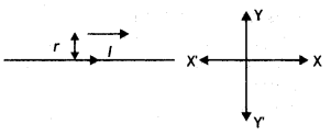
Find the magnitude and direction of the electric field required so that the particle goes undefeated. (CBSE Sample Paper 2018-19)
Answer:
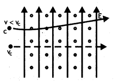
If the ion passes undeflected, therefore the magnetic and electric forces acting on the ion must be equal and opposite.
Therefore
qE = Bqvc
vc = \(\frac{E}{B}\)
The trajectory would be as shown. Justification: For positive ions with speed v < vc. Force due to electric field wilt remains the same as It does not depend upon Vc.
But force due to the magnetic field will become Less than the initial value. This unbalances the two, electric and magnetic, forces hence, the ion will experience a net electric force. This will accelerate the ion along the direction of the electric field. Since initiaL velocity is perpendicular to E, the trajectory would be parabolic.
OR
For the charged particle to move undeflected
Electric force = magnetic force
qE = Bq v
or
E=Bv
Now magnetic field at a distance r from the long straight conductor is
B = \(\frac{\mu_{0} I}{2 \pi r}\)
This magnetic force Will act towards the wire.
Hence electric field is
E = \(\frac{\mu_{0} l v}{2 \pi r}\)
This electric field should act away from the wire.
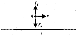
Numerical Problems:
Formulae for solving numerical problems
- Magnetic field due to a small current element dB = \(\frac{\mu_{0}}{4 \pi} \frac{l mid d L \sin \theta}{r^{2}}\)
- Magnetic field due to an infinitely long straight conductor B = \(\frac{\mu_{0}}{4 \pi} \frac{2l}{a}\)
- Magnetic field at the centre of a circular coil B = \(\frac{\mu_{0}}{4 \pi} \frac{2 \pi l}{r}\)
- Force on a charge moving in a magnetic field F = Bq v Sin θ
- The magnetic field inside a solenoid B = µ0 n I
- Force on a current-carrying conductor placed in a magnetic field F = BIL Sin θ
- Force between two current carrying conductors \(\frac{F_{1}}{L}=\frac{\mu_{0} l_{1} l_{2}}{2 \pi a}\)
- Torque on a current loop τ = BI n A sin θ
- Current in a galvanometer l = \(\frac{C}{n B A}\) sin θ
- Shunt required S = \(\frac{l_{8} G}{l-I_{g}}\)
- Resistance required R = \(\frac{v}{l_{g}}\) – G
- Radius of a charged particle in a magnetic field r = \(\frac{m v}{B q}=\frac{\sqrt{2 m E}}{B q}\)
Question 1.
A proton and an alpha particle having the same kinetic energy are in turn allowed to pass through a uniform magnetic field perpendicular to their direction of motion. Compare the radii of the paths of the proton and the alpha particle.
Answer:
Given Eα = Ep, mα = 4 mp, qα = 2qp, B is same for both. Now the radius of the path followed is given by the expression
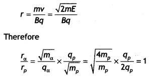
Question 2.
A circular coil of 30 turns and radius 8.0 cm carrying a current of 6.0 A is suspended vertically in a uniform horizontal magnetic field of magnitude 1.0 T. The field lines make an angle of 60° with the normal to the coil. Calculate the magnitude of the counter-torque that must be applied to prevent the coil from turning.
Answer:
Given n = 30, r = 8.0 cm = 8 × 10⁻² m,
l = 6.0 A, B = 1.0 T, θ = 60°, τ = ?
Using the formula for torque
τ = BlnA
we have τ = Blnπr² sin θ
τ = 1 × 6 × 30 × 3.14 × (8 × 10-2)2 × sin 60°
= 3.1 N m
Question 3.
How can a moving coil galvanometer be converted into an ammeter? To increase the current sensitivity of a moving coil galvanometer by 50%, its resistance is increased so that the new resistance becomes twice its initial resistance. By what factor does its voltage sensitivity change?
Answer:
Voltage sensitivity
= \(\frac{\alpha}{V}=\frac{\alpha}{I R}=\frac{\text { current sensitivity }}{R}\)
When the current sensitivity increases by 50 % resistance becomes 2R.
New voltage sensitivity
= \(\frac{1+0.5}{2}\) = 0.75
Hence the voltage sensitivity decreases and becomes 75% of its original value.
Question 4.
A long straight conductor PQ carrying a current of 75 A is fixed horizontally. Another long conductor XY is kept parallel to PQ at a distance of 5 mm, in air. Conductor XY is free to move and carries a current l. Calculate the magnitude and direction of current l for which the magnetic repulsion just balances the weight of conductor XY (Mass per unit length for conductor XY is 10-2 kg m-1.)

Answer:
Given l1 = 75 A, r = 5 mm = 5 × 10⁻³ m, l2 = ? mass per unit length = 10-2kg m-1.
The force between the two wires should be repulsive and should balance the weight of the wire XY. Thus the current in wire XY will be opposite to that in wire PQ.
The force between the two current-carrying conductors is given by
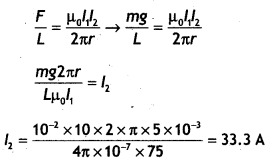
Question 5.
A galvanometer has a resistance of 30 Ω. It gives full-scale deflection with a current of 2 mA. Calculate the value of the resistance needed to convert it into an ammeter of range 0-0.3 A.
Answer:
Given G = 30 Ω, lg = 2 mA= 2 × 10⁻³ A, S = ?, I = 0.3 A
Using the formula S = \(\frac{I_{g} G}{I-I_{g}}\)
we have
S = \(\frac{I_{g} G}{I-I_{g}}\) = \(\frac{30 \times 2 \times 10^{-3}}{0.3-2 \times 10^{-3}}\) = 0.20 Ω
Question 6.
An infinitely long straight current-carrying wire produces a magnetic field 8, at a point distant ‘a’ from it. What must be the radius of a circular loop, so that, for the same current through it, the magnetic field at (i) its center equals B/2 and (ii) an axial point, distant equal to the radius of the loop, equals B?
Answer:
The magnetic field at a distance ‘a’ from an infinitely long straight conductor is
B = \(\frac{\mu_{0} I}{2 \pi a}\)
(i) Given Bc = B/2. Let r be the radius of the circular coil for which the magnetic field is B/2.
Magnetic field at the centre of a circular coil is \(B=\frac{\mu_{0} I}{2 \pi a}\) Therefore
\(\frac{\mu_{0} l}{2 r}=\frac{1}{2} \times \frac{\mu_{0} l}{2 \pi a}\) or r = 2 π a
(ii) Magnetic field at the axial line of a loop is
B = \(\frac{\mu_{0} l R^{2}}{2\left(x^{2}+R^{2}\right)^{1 / 2}}\)
Here x = R radius of the loop.
Therefore \(\frac{\mu_{0} I}{2 \pi a}=\frac{\mu_{0} I R^{2}}{2\left(R^{2}+R^{2}\right)^{3 / 2}}\)
solving for R we have R = \(\frac{\pi a}{\sqrt{8}}\)
Question 7.
Calculate the value of resistance needed to convert a galvanometer of resistance 120 ft, which gives a full-scale deflection for a current of 5 mA, into a voltmeter of 0 – 50 V range.
Answer:
Given G = 120 Ω, lg = 5 × 10⁻³A, V= 50 V, R =?
Using the relation R = \(\frac{v}{l_{g}}\) – G we have
R = \(\frac{50}{5 \times 10^{-3}}\) -120 = 9880 Ω
Question 8.
Two infinitely long straight wires A1 and A2 carrying currents l1 and l2 flowing in the same directions are kept distance apart. Where should a third straight wire A3 carrying current 1.5 l be placed between A1 and A2 so that it experiences no net force due to A1 and A2? Does the net force act on A3 depend on the current flowing through it? (CBSE Delhi 2019)
Answer:
The diagram is as shown.
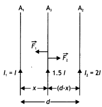
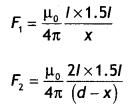
If no force is experienced by the conductor A3, then
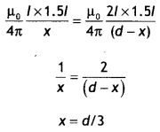
The net force on A3 does not depend upon the current flowing through it.
Question 9.
An ammeter of resistance 0.80 Ω can measure current up to 1.0 A.
(a) What must be the value of shunt resistance to enable the ammeter to measure current up to 5.0 A?
Answer:
Given G = 0.80 Ω, /g = 1.0 A, l = 5.0 A, S = ?, R<sub>A</sub> = ?
(a) Using the expression
S = \(\frac{I_{g} G}{I-I_{0}}=\frac{1 \times 0.8}{5-1}=\frac{0.8}{4}\) = 0.2 Ω
(b) What is the combined resistance of the ammeter and the shunt? (CBSE Delhi 2013)
Answer:
Now RA = \(\frac{G S}{G+S}=\frac{0.8 \times 0.2}{0.8+0.2}\) = 0.016 Ω
Question 10.
A wire AB is carrying a steady current of 12 A and is lying on the table. Another wire CD carrying 5A is held directly above AB at a height of 1 mm. Find the mass per unit length of the wire CD so that it remains suspended at its position when left free. Give the direction of the current flowing in CD with respect to that in AB. (Take the value of g = 10 m s-2) (CBSE AI 2013)
Answer:
Given l1 = 12 A, r = 1 mm = 1 × 10⁻³ m, l2 = 5 A, mass per unit length = ?
The force between the two wires should be repulsive and should balance the weight of the wire CD. Thus the current in wire CD will be opposite to that in wire AB.
The force between the two current¬carrying conductors is given by
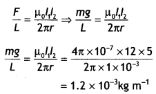
Question 11.
A square loop of side 20 cm carrying a current of I A is kept near an infinitely long straight wire carrying a current of 2 A in the same plane as shown in the figure.
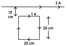
Calculate the magnitude and direction of the net force exerted on the loop due to the current carrying conductor. (CBSEAI 2015C)
Answer:
Here, PQ = 20 cm = 20 × 10-2 m,
PS = 20 cm = 10 × 10-2 m
Distance of PQ from AB,
r1 = 10 cm = 10 × 10-2 m
Distance of RS from AB,
r2 = (10 + 20) = 30 cm = 30 × 10-2 m
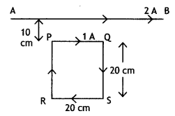
Current through long wire AB, l1 = 2 A
Current through rectangular loop, l2 = 1 A
Force on the arm PQ,
F1 = \(\frac{\mu_{0} I_{1} I_{2}}{2 \pi a}\) × length PQ
F2 = \(\frac{2 \times 10^{-7} \times 2 \times 1 \times 20 \times 10^{-2}}{10 \times 10^{-2}}\) = 8 × 10⁻⁷ N
= 8 × 10⁻⁷ N (towards AB)
Force on the arm RS,
F1 = \(\frac{\mu_{0} I_{1} I_{2}}{2 \pi a}\) × length RS
F2 = \(\frac{2 \times 10^{-7} \times 2 \times 1 \times 20 \times 10^{-2}}{30 \times 10^{-2}}\) =2.66 × 10-7
= 2.66 × 10⁻⁷ N (away from AB)
Effective force on the Loop,
F= F1 – F2
=8 × 10⁻⁷ – 2.66 × 10-7
= 5.34 × 10⁻⁷ N (towards AB)
Question 12.
A square-shaped plane coil of area 100 cm2 of 200 turns carries a steady current of 5A. It is placed in a uniform magnetic field of 0.2 T acting perpendicular to the plane of the coil. Calculate the torque on the coil when its plane makes an angle. of 60° with the direction of the field. In which orientation will the coil be in stable equilibrium? (CBSE Al 2015C)
Answer:
Given A= 10-2 m², n = 200, l = 5 A, θ = 60°, B = 0.2 T, τ = ?
Using the expression τ = B I n A sin θ we have
τ = 0.2 × 5 × 200 × 10-2 × sin 60° = 20 Nm
Stable equilibrium, when the magnetic field is in the direction of the coil.
Question 13.
A straight wire of mass 200 g and length 1.5 m carries a current of 2 A. It is suspended in mid-air by a uniform horizontal magnetic field B (figure). What is the magnitude of the magnetic field? (NCERT)
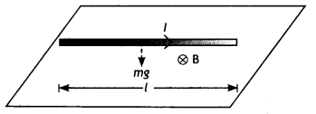
Answer:
For the wire to be suspended in mid-air, it must experience an upward force F of magnitude F = B I L to balance its weight W= mg
Therefore, BI L = mg
B = \(\frac{m g}{1 L}=\frac{0.2 \times 9.8}{2 \times 1.5}\) = 0.65 T
Question 14.
A cyclotron’s oscillator frequency is 10 MHz. What should be the operating magnetic field for accelerating proto is? If the radius of its dees is 60 cm what is the kinetic energy (in m MeV) of the proton beam produced by the accelerator (e =1.60 × 10⁻¹⁹ C, mp = 1.67 × 10⁻²⁷ kg, 1 MeV = 1.6 × 10⁻¹³ J) (NCERT)
Answer:
The oscillator frequency should be the same as the proton’s cyclotron frequency, i.e. 10 MHz = 107 Hz.
Therefore
B = \(\frac{2 \pi m v}{q}\)
= \(\frac{2 \times 3.14 \times 1.67 \times 10^{-27} \times 10^{7}}{1.6 \times 10^{-19}}\) = 0.66 T
Final velocity of protons is
V = r × 2πv = 0.6 × 6.3 × 107 = 3.78 × 10⁷ m s-1.
E = 1/2mv² = 1.67 × 10-27 × 14.3 × 1014 / (2 × 1.6 × 10-13) = 7 MeV
Question 15.
A solenoid of length 0.5 m has a radius of 1 cm and is made up of 500 turns. Does it carry a current of 5 A. What is the magnitude of the magnetic field inside the solenoid? (NCERT)
Answer:
Given n = 500/0.5 = 1000 turns per unit length. l = 5 A
The length L = 0.5 m and radius r = 0.01 m. Thus, L/a = 50,
Hence we have
B = μonl = 4π x 10-7 × 1000 × 5 = 6.28 × 10⁻³ T
Question 16.
A circular coil of wire consisting of 100 turns, each of a radius 8.0 cm, carries a current of 0.40 A. What is the magnitude of the magnetic field B at the center of the coil? (NCERT)
Answer:
Given n = 100, r = 8.0 cm = 8.0 × 10⁻² m,
l = 0.40 A,B = ?
Using the expression B = \(\frac{\mu_{0} n l}{2 r}\)
we have
B = \(\frac{\mu_{0} n l}{2 r}=\frac{4 \pi \times 10^{-7} \times 100 \times 0.40}{2 \times 8.0 \times 10^{-2}}\)
Question 17.
A horizontal overhead power line carries a current of 90 Ain the east to west direction. What is the magnitude and direction of the magnetic field due to the current 1.5 m below the line? (NCERT)
Answer:
Given l = 90 A, r = 1.5 m, B = ?
Using the expression B = \(\frac{\mu_{0} l}{2 \pi r}\) we have
B = \(\frac{\mu_{0} l}{2 \pi r}=\frac{4 \pi \times 10^{-7} \times 90}{2 \times \pi \times 1.5}\) = 1.2 × 10⁻⁵ T
The magnetic field will be towards the south.
Question 18.
A square coil of side 10 cm consists of 20 turns and carries a current of 12 A The coil is suspended vertically and the normal to the plane of the coil makes an angle of 30° with the direction of a uniform horizontal magnetic field of magnitude 0.80 T. What is the magnitude of torque experienced by the coil? (NCERT)
Answer:
Given L= 10 cm=0.1 m, A = (0.1)² = 0.01 m², n = 20 , l = 12 A, θ = 30°, B = 0.80T, τ = ?
Using the expression τ = B l n A sin θ we have
τ = 0.80 × 12 × 20 × 0.01 × sin 30° = 0.96 Nm
Question 19.
A straight horizontal conducting rod of length 0.45 m and mass 60 g is suspended by two vertical wires at its ends. A current of 5.0 A is set up in the rod through the wires.
(i) What magnetic field should be set up normally to the conductor in order that the tension in the wires is zero?
(ii) What will be the total tension in the wires if the direction of the current is reversed keeping the magnetic field the same as before? (Ignore the mass of the wires.) g = 9.8 ms-2 (NCERT)
Answer:
Given L = 0.45 m, m = 60 g, I = 5.0 A, B = ?
(i) The tension in the wires will be zero if the weight of the rod is balanced by the force on it due to the magnetic field.
Therefore we have
B I L = mg
B = \(\frac{m g}{I L}=\frac{0.06 \times 9.8}{5.0 \times 0.45}\) = 0.26 T
Thus a horizontal magnetic field of magnitude 0.26 T normal to the conductor should be applied in such a direction that Fleming’s left-hand rule gives a magnetic force in the upward direction.
(ii) The tension will become twice the weight of the wire i.e.,
T = B / L + mg = mg + mg = 2 mg
Or
T= 2 × 0.06 × 9.8 = 1.176 N
Question 20.
A galvanometer coil has a resistance of 12 ohms and the meter shows full-scale deflection for a current of 3 mA. How will you convert the meter into a voltmeter of range 0 to 18 V? (NCERT)(CBSE 2019C)
V= 18 V, R = ?
We will connect a resistance R = \(\left(\frac{V}{l_{g}}-G\right)\) in series with the galvanometer.
Therefore R = \(\frac{18}{3 \times 10^{-3}}\) – 12 = 5988 Ω
Question 21.
A galvanometer coil has a resistance of 15 ohms and the meter shows full-scale deflection for a current of 4 mA. How will you convert the meter into an ammeter of range 0 to 6A? (NCERT)
Answer:
Given G = 15 Ω, lg = 4 mA = 4 × 10⁻³ A, l = 6 A, S = ?
We will connect a resistance S = \(\frac{l_{s} G}{l-l_{s}}\) in parallel with the galvanometer.
Therefore S = \(\frac{4 \times 10^{-3} \times 15}{6-\left(4 \times 10^{-3}\right)}\) = 0.01 Ω
Or
S = 10 mΩ