Resistance of A System of Resistors
There are two methods of joining the resistors together. The figure below shows an electric circuit in which three resistors having resistances R1, R2, and R3, respectively, are joined end to end. Here the resistors are said to be connected in series.
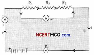
Figure below shows a combination of resistors in which three resistors are connected together between points X and Y. Here, the resistors are said to be connected in paralleL
Resistors in Series
If the resistors are connected in such a way that there is only one path through current flows, they are said
to be connected in series. The potential difference V is equal to the sum of the potential differences V1, V2 and V3. That is the total potential difference across a combination of resistors in series is equalto the sum of the potential difference across the individual resistors. That is,
V = V1 + V2 + V3
The effective resistance in series combination is given by R = R1 + R2 + R3
![]()
Resistors in Parallel
If the resistors are connected in such a way that the potential difference across each resistor is same, they are said to be connected in parallel.
Example 1.
Case Based:
Make a parallel combination, XY, of three resistors having resistances R1, R2, and R3, respectively. Connect it with a battery, a plug key, and an ammeter, as shown in Figure below.
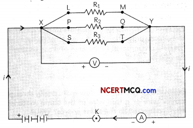
Also connect a voltmeter in parallel with the combination of resistors.
Let us take resistances R1, R2, and R3 of values 2 Ω, 4 Ω and 12 Ω respectively and let V = 6 V.Plug the key and note the ammeter reading. Let the current be I. Also, take the voltmeter reading. It gives the potential difference V, across the combination. The potential difference across each resistor is also V.
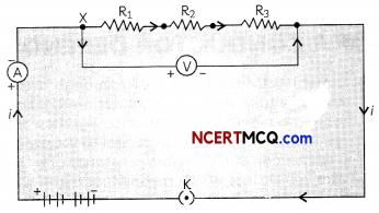
Take out the plug from the key. Remove the ammeter and voltmeter from the circuit. Insert the ammeter in series with the resistor R1, as shown in Figure below.
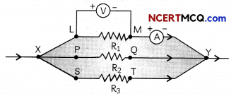
Note the ammeter reading, li. Similarly, measure the currents through R2 and R3. Let these be I2 and I3, respectively.
(A) Refer to Figure in the given activity. A student recorded the readings of voltmeter and am¬meter in a table as given below. Select the row containing correct observations.
| Reading of Voltmeter (V) (Volt) | Reading of Ammeter (1) (Amp) |
| (a) 6 V | 7.2 A |
| (b) 6 V | 5 A |
| (c) 3 V | 10 A |
| (d) 3 V | 1.5 A |
(a) Both (A) and (R) are true and (R) is the correct explanation of the (A).
(b) Both (A) and (R) are true, but (R) is not the correct explanation of the (A).
(c) (A) is true, but (R) is false.
(d) (A) is false, but (R) is true.
Answer:
(b) Reading of Voltmeter: 6V; Reading of Ammeter: 5 A
Explanation: The reading of voltmeter = 6 V and reading of ammeter = 5 A as the resistances are connected in parallel and the current across the resistors R1, R2 and R3 will be 6/2 or 3 A, 6/4 or 1.5 A and 6/12 or 0.5 A respectively. Therefore, total current will be 5 A. Voltmeter reading will be the potential difference = 6 V.
(B) The reading of the ammeter when it is connected in series with the resistor Rl is:
(a) 0.5 A
(b) 1.5 A
(c) 3A
(d) 5A
Answer:
(c) 3 A
Explanation: When the ammeter is connected in series with the resistor R1, it will show the current flowing li through the resistor R1 which can be found by using Ohm’s law.
V = I1R1
⇒ I1 = \(\frac{V}{R_{1}}=\frac{6}{2}\) = 3A
(C) What is the reLation between the totaL current and the currents fLowing in each of the resistors?
Answer:
The total current I is equal to the sum of the currents flowing in each of the resistors. If I1 is the total current and the current flowing in resistors R1, R2 and R3 is given by I1, I2 and I3 respectively, then I = I1 + I2 + I3.
(D) What is the reLation between the current flowing in resistors R2 and R3 and their resistances?
Answer:
The currents I2 and I3 flowing in resistors R2 and R3 respectively are calculated by using Ohm’s law, keeping in mind that V is same for all resistors connected in parallel.
I2 = \(\frac{\mathrm{V}}{\mathrm{R}_{2}}=\frac{6}{4}\)A = 1.5 A
and I2 = \(\frac{V}{R_{3}}=\frac{6}{12}\)A = 0.5A
Ratio of I2: I3 = 1.5 : 0.5 = 3: 1 whereas ratio of R2 : R3 = 4: 12 = 1 : 3.
Therefore, we can conclude that the currents I2 and I3 flowing in resistors R2 and R3 respectively are inversely proportional to the resistances.
(E) Assertion (A): The ammeter readings will be different when connected through any of the resistors R1, R2 or R3.
Reason (R): The current flowing through any resistor can be found by using Ohm’s Law.
Reading of Voltmeter (V): 6 V; Reading of Ammeter (I): 5 A
Answer:
(b) Both (A) and (R) are true, but (R) is not the correct explanation of the (A).
Explanation: The ammeter readings wilt be different when connected through an of the resistors R1. R2 or R3 os the potential diffrenœ across the resistors in parallel is same but current divides itself into the branches inversely as the resistance in that branch.
This means that each branch current is inversely proportional to its resistanœ resulting in the smaller resistance having the larger current Ohms law is used to find the current flowing in each branch through any resistor.
The total current I is equal to the sum of the separate currents through each branch of the combination. I = I1 + I2 + I3.
The effective resistance in parallel combination is given by \(\frac{1}{R}=\frac{1}{R_{1}}+\frac{1}{R_{2}}+\frac{1}{R_{3}}\)
![]()
Example 2.
An electric lamp of 100 D, a toaster of resistance 50 Ω, and a water filter of resistance 500 Ω are connected in parallel to a 220 V source. What is the resistance of an electric iron connected to the same source that takes as much current as all three appliances, and what is the current through it?
Answer:
Let the resistance of the electric lamp, toaster, and water filter be denoted by R1, R2, and R3 respectively.
Then, R1 = 100 Ω, R2 = 50 Ω and R3 = 500 Ω.
As the three appliances are connected in parallel, the resistance of an electric iron connected to the same source should be equal to the equivalent resistance of the three appliances in parallel (since the current is the same).
Equivalent resistance is given by
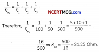
Therefore, resistance of an electric iron connected to the same source that takes as much current as all three appliances = 31.25 Ohm.
Current through the iron is calculated using
Ohms Law,V = IR or I = \(\frac{V}{R}=\frac{220}{31.25}\) =7.04A
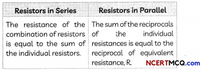
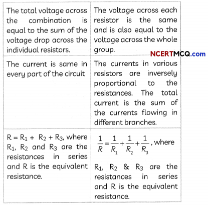
Comparison of Resistors in Series and Parallel
![]()
Example 3.
How can three resistors of resistances 2 Ω, 3 Ω, and 6 Ω be connected to give a total resistance of (a) 4 Ω, (b) 1 Ω?
Answer:
(a) For getting a total resistance of 4 Ω, we should connect the resistors as shown below:
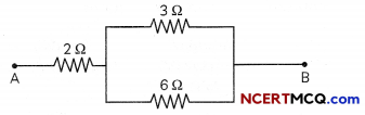
The equivalent resistance of the parallel combination of 3 Ω and 6 Ω is given by
\(\frac{1}{R_{e q}}=\frac{1}{3}+\frac{1}{6}=\frac{2+1}{6}=\frac{3}{6}\) ⇒ Req = 2 Ω
When this combination is connected with a 2 Ω resistor, the total resistance = 2 + 2 = 4Ω.
(b) For getting a total resistance of 1 Ω, we should connect all the resistors in parallel as shown below
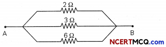
The equivalent resistance of three resistors in parallel is given by \(\frac{1}{R_{e q}}=\frac{1}{R_{1}}+\frac{1}{R_{2}}+\frac{1}{R_{3}}=\frac{1}{2}+\frac{1}{3}+\frac{1}{6}\)
= \(\frac{3+2+1}{6}=\frac{6}{6}\) ⇒ 1 Req = 1Ω