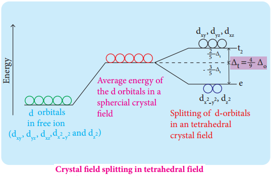
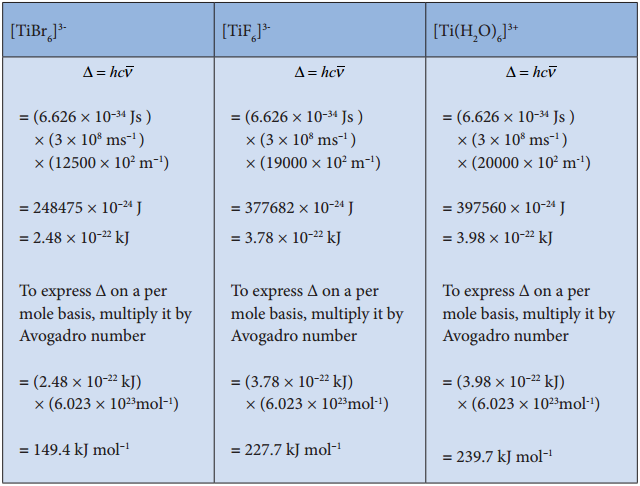
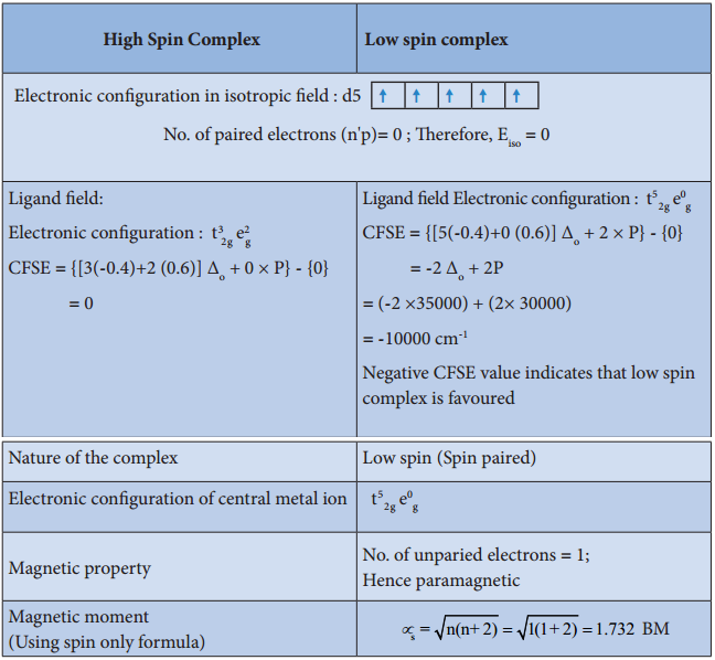
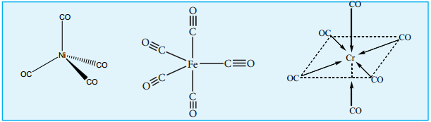
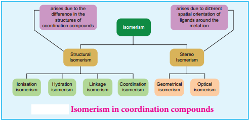
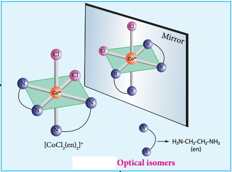
Find free online Chemistry Topics covering a broad range of concepts from research institutes around the world.
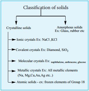
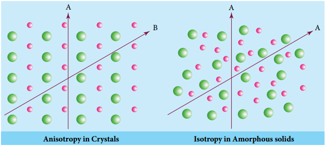
Classification of Crystalline Solids
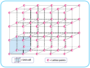
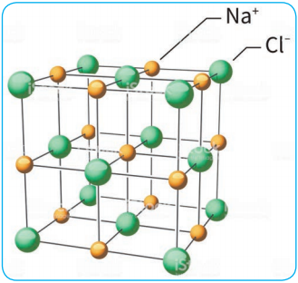
The structural units of an ionic crystal are cations and anions. They are bound together by strong electrostatic attractive forces. To maximize the attractive force, cations are surrounded by as many anions as possible and vice versa. Ionic crystals possess definite crystal structure; many solids are cubic close packed. Example: The arrangement of Na+ and Cl– ions in NaCl crystal.
Characteristics:
- Ionic solids have high melting points.
- These solids do not conduct electricity, because the ions are fixed in their lattice positions.
- They do conduct electricity in molten state (or) when dissolved in water because, the ions are free to move in the molten state or solution.
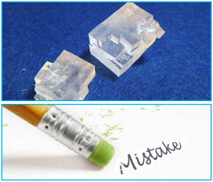
- They are hard as only strong external force can change the relative positions of ions.
Covalent Solids:
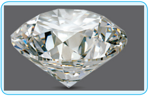
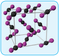
In covalent solids, the constituents (atoms) are bound together in a three dimensional network entirely by covalent bonds. Examples: Diamond, silicon carbide etc. Such covalent network crystals are very hard, and have high melting point. They are usually poor thermal and electrical conductors.
Molecular Solids:
In molecular solids, the constituents are neutral molecules. They are held together by weak vander Waals forces. Generally molecular solids are soft and they do not conduct electricity. These molecular solids are further classified into three types.
(i) Non-Polar Molecular Solids:
In non polar molecular solids constituent molecules are held together by weak dispersion forces or London forces. They have low melting points and are usually in liquids or gaseous state at room temperature. Examples: naphthalene, anthracene etc.,
(ii) Polar Molecular Solids
The constituents are molecules formed by polar covalent bonds. They are held together by relatively strong dipole-dipole interactions. They have higher melting points than the nonpolar molecular solids. Examples are solid CO2, solid NH3 etc.
(iii) Hydrogen Bonded Molecular Solids
The constituents are held together by hydrogen bonds. They are generally soft solids under room temperature. Examples: solid ice (H2O), glucose, urea etc.,
Metallic Solids:
You have already studied in XI STD about the nature of metallic bonding. In metallic solids, the lattice points are occupied by positive metal ions and a cloud of electrons pervades the space. They are hard, and have high melting point. Metallic solids possess excellent electrical and thermal conductivity. They possess bright lustre. Examples: Metals and metal alloys belong to this type of solids, for example Cu, Fe, Zn, Ag, Au, CuZn etc.