Electromagnetic Induction
In 1831, Faraday made an important breakthrough by discovering how a moving magnet ran be used to generate electric currents. The phenomenon of inducing current in a coil by a changing magnetic field is called electromagnetic induction. The magnetic field be changed when there is a relative motion between the coil and the magnet.
Galvanometer: It is an instrument that can detect the presence of current in a circuit. The pointer remains at zero (centre of the scale) if no current flows through it and deflects to either the left or right of the zero mark depending on the direction of current.
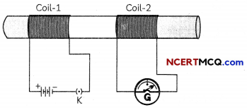
Explanation of Electromagnetic Induction
A current is induced in the secondary coil whenever the current in the primary coil is changing because the magnetic field associated with the primary coil changes. The induced current is found to be the highest ‘when the direction of motion of the coil is at right angles to the magnetic field.
![]()
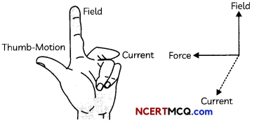
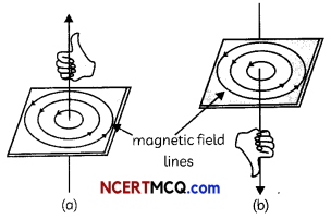
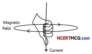
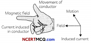
Fleming’s Right Hand Rule
The direction of Induced current is given by Fleming’s Right Hand Rule. Hold the forefinger, the central finger and the thumb of the right hand perpendicular to each other so that the forefinger indicates the direction of the field, and the thumb is in the direction of motion of the conductor. Then, the central finger shows the direction of current induced in the conductor.
Example 1.
A coil of insulated copper wire is connected to a galvanometer. What will happen if a bar magnet is (A) pushed into the coil, (B) withdrawn from inside the coil, (C) held stationary inside the coil?
Answer:
(A) If a bar magnet is pushed into the coil of in-sulated copper wire, the galvanometer will show the deflection as current is induced in the coil due to the relative motion between the coil and the magnet.
(B) When the bar magnet is withdrawn from the coil the galvanometer shows deflection again but now to the opposite side, as direction of induced current is in an opposite direction,
(C) When the bar magnet is held stationary inside the coil, the galvanometer does not show any deflection as no current is induced in the coil since there is no change in magnetic field linked with the coil.
![]()
Example 2.
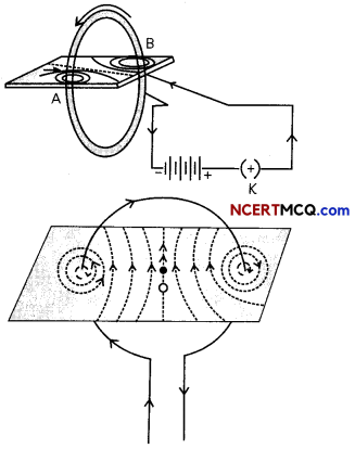
Two circular coils A and B are placed close to each other. If the current in the coil A is changed, will some current be induced in coil B? Give a reason.
Answer:
Yes, some current will be induced in coil B when current in coil A is changed. This is be¬cause a changing current in coil A will change the magnetic field in coil A and as coil A and B are placed close to each other, the magnetic field linked with the coil B will also change and hence current will be induced in coil B.