NCERT Exemplar Solutions for Class 10 Science Chapter 12 Electricity
These Solutions are part of NCERT Exemplar Solutions for Class 10 Science. Here we have given NCERT Exemplar Solutions for Class 10 Science Chapter 12 Electricity
Question 1.
A cell, a resistor, a key and ammeter are arranged as shown in the circuit diagrams of the figure given below. The current recorded in the ammeter will be
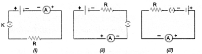
(a) maximum in (i)
(b) maximum in (ii)
(c) maximum in (iii)
(d) the same in all the cases.
Answer:
(d).
Explanation : Same current flows through every part of the circuit having resistance connected in series to a cell or battery.
More Resources
- NCERT Exemplar Solutions for Class 10 Science
- NCERT Solutions for Class 10 Science
- Value Based Questions in Science for Class 10
- HOTS Questions for Class 10 Science
- Previous Year Question Papers for CBSE Class 10 Science
Question 2.
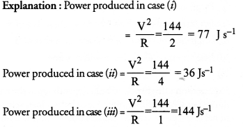
In the following circuits shown in figure, power produced in the resistor or combination of resistors connected to a 12V battery will be
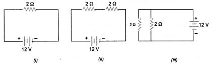
(a) same in all cases
(b) minimum in case (i)
(c) maximum in case (ii)
(d) maximum in case (iii)
Answer:
(d).
Question 3.
Electrical resistivity of a given metallic wire depends upon
(a) its length
(b) its thickness
(c) its shape
(d) nature of material.
Answer:
(d).
Explanation : Resistivity of a given metallic wire does not depend on its dimensions and shape but depends on the nature of the material of the wire.
Question 4.
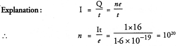
A current of 1A is drawn by a filament of an electric bulb. Number of electrons passing through a cross-section of the filament in 16 seconds would be roughly
(a) 1020
(b) 1016
(c) 1018
(d) 1023
Answer:
(a).
Question 5.
Identify the circuit (Figure) in which electrical components have been properly connected.
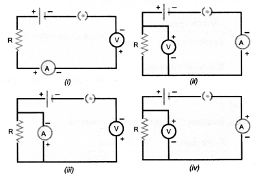
(a) (i)
(b) (ii)
(c) (iii)
(d) (iv)
(CBSE 2010)
Answer:
(b).
Explanation : Voltmeter is always connected in parallel and ammeter is connected in series in an electric circuit. Moreover, positive terminals of voltmeter and ammeter are connected with the +ve terminal of a cell or battery and negative terminals of voltmeter and ammeter are connected with -ve terminal of a cell or battery.
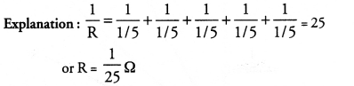
Question 6.
What is the maximum resistance which can be made using five resistors each 1/5 Ω ?
(a) 10 Ω
(b) 10 Ω
(c) 5 Ω
(d) I Ω (CBSE 2010)
Answer:
(d).
![]()
Question 7.
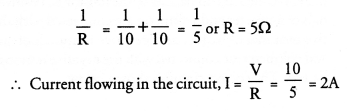
What is the minimum resistance which can be made using 1 five resistors each of 1/5 Ω ?
![]()
Answer:
(d).
Question 8.
The proper representation of series combination of cells obtaining maximum potential is
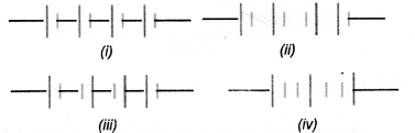
(a) (i)
(b) (ii)
(c) (iii)
(d) (iv)
(CBSE 2011,2012)
Answer:
(d).
Explanation : Cells are connected in series if -ve terminal of one cell is connected to the +ve terminal of other cell.
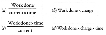
Question 9.
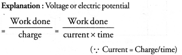
Which of the following represents voltage ?
Answer:
(a).
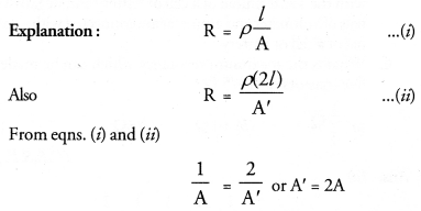
Question 10.
A cylindrical conductor of length l and uniform area of cross-section A has resistance R. Another conductor of length 2l and resistance R of the same material has area of cross-section.
(a) A/2
(b) 3A/2
(c) 2A
(d) 3A
Answer:
(c).
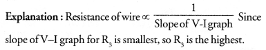
Question 11.
A student carries out an experiment and plots the V—I graph of three samples of nichrome wire with resistances R1, R2 and R3 respectively as shown in figure. Which of the following is true ?
(a) R1 = R2 = R3
(b) R1 > R2 > R3
(c) R3 > R2 > R1
(d) R2 > R3 > R1
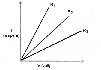
Answer:
(c).
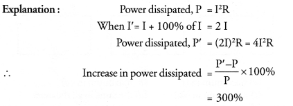
Question 12.
If the current I through a resistor is increased by 100% (assume that temperature remains unchanged), the increase in power dissipated will be
(a) 100 %
(b) 200%
(c) 300%
(d) 400%
Answer:
(c).
Question 13.
The resistivity does not change if
(a) the material is changed
(b) the temperature is changed
(c) the shape of the resistor is changed
(d) both material and temperature are changed.
Answer:
(c).
Explanation : Resistivity of material does not depend on its di¬mensions and shape. However, resistivity depends upon the tem¬perature and the nature of material.
Question 14.
In an electrical circuit, three incandescent bulbs A, B and C of rating 40 W, 60 W and 100 W respectively are connected in parallel to an electric source. Which of the following is likely to happen regarding their brightness ?
(a) Brightness of bulb A will be maximum
(b) Brightness of bulb B will be more than that of A
(c) Brightness of bulb C will be less than that of B
(d) Brightness of all the bulbs will be same
Answer:
(b).
Explanation : Brightness of bulb depends upon the heat produced per second. Since resistance of bulb is inversely proportional to the power, so resistance of bulb A is more than that of B and resistance of bulb B is more than that of C. Heat produced per second = V2/R
where V is same for all bubls.
Therefore, brightness of bulb B is more than that of A.
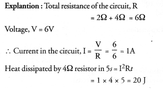
Question 15.
In an electrical circuit two resistors of 2Ω and 4Ω respectively are connected in series to a 6V battery. The heat dissipated by 4Ω resistor in 5 s will be
(a) 5 J
(b) 10 J
(c) 20 J
(d) 30 J
Answer:
(c).
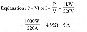
Question 16.
An electric kettle consumes 1 kW of electric power when operated at 220 V. A fuse wire of what rating must be used for it ?
(a) 1 A
(b) 2 A
(c) 4 A
(d) 5 A
Answer:
(d).
Question 17.
Two resistors of resistance 2Ω and 4Ω when connected to a battery will have
(a) same current flowing through them when connected in parallel
(b) same current flowing through them when connected in series.
(c) same potential difference across them when connected in series
(d) different potential difference across them when connected in parallel
Answer:
(b)
Explanation : Resistors are said to be connected in series if same current flows through them as series combination has a single path for the flow of current. Resistors are said to be connected in parallel if potential difference across them is
Question 18.
Unit of electric power may also be expressed as
(a) Volt ampere
(b) kilowatt hour
(c) watt second
(d) joule second
Answer:
(a).
Explanation : P = VI.
Question 19.
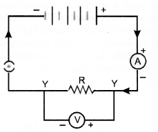
A child has drawn the electric circuit to study Ohm’s law as shown in figure. His teacher told that the circuit diagram needs correction. Study the circuit and redraw it after making all corrections.
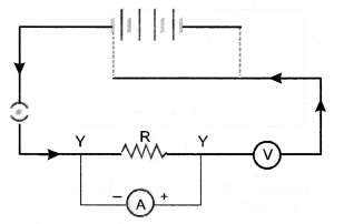
Answer:
Ammeter is connected in series in an electric circuit and volt¬meter is connected in parallel to the resistor R. Positive terminals of ammeter and voltmeter are connected with the positive terminal of battery and negative terminals of ammeter and voltmeter are connected with the negative terminal of the battery. The correct circuit is shown below.
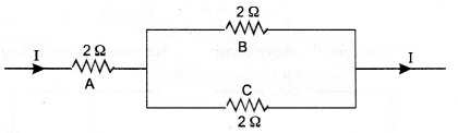
Question 20.
Three 20 resistors, A, B and C are connected as shown in figure. Each of them dissipates energy that can withstand a maximum power of 18W without melting. Find the maximum current that can flow through three resistors.
(CBSE, 2010)
Answer:
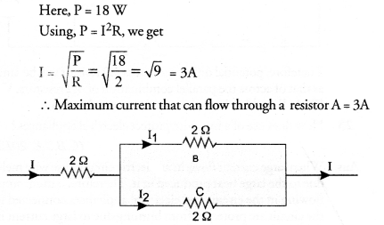
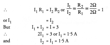
Since resistors B and C are connected in parallel, so potential difference across B and C is same. Let I1, be the current flowing through resistor.B and I2 be the current flowing through resistor C
Question 21.
Should the resistance of an ammeter be low or high ? Give reason.
Answer:
Ammeter is connected in series in an electric circuit to measure electric current. If its resistance is high, then the net resistance of the electric circuit will increase and hence current in the electric circuit will decrease. Hence, ammeter will not read the actual value of the current in the circuit. If resistance of the ammeter is low, then the net resistance of the circuit will not be effected much. Hence, the current in the circuit is not affected. Ideal ammeter has zero resistance.
Question 22.
Draw a circuit diagram of an electric circuit containing a cell, a key, an ammeter, a reistor of 2Ω in series with a combination of two resistors (4Ω each) in parallel and a voltmeter across the energy. 1 kWh = 1000 Watt x 3600 s parallel combination. Will the potentional difference across the 2Ω resistor be the same as that across the parallel combination of 4Ω resistors ? Give reason.
Answer:
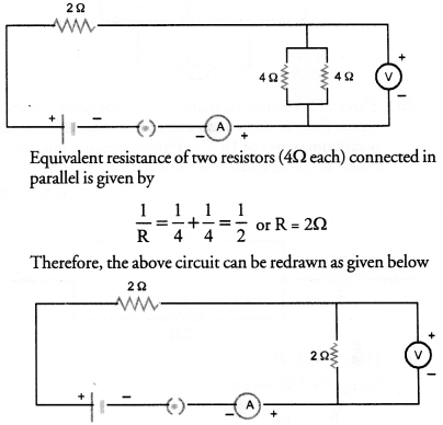
Therefore, potential difference across 2Ω resistor will be same ; as that of across the parallel combination of 4Ω resistors. V = IR.
As R and I in both the cases is same so V = same.
Question 23.
How does use of a fuse wire protect electrical appliances ?
(CBSE 2012)
Answer:
When large current flows in an electric circuit, fuse wire melts due to the large heat produced in it. Therefore, current stops flowing in the circuit and electrical appliances connected in the circuit are protected from burning due to large current in j the circuit.
Question 24.
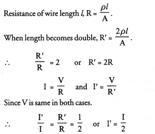
In a series electrical circuit comprising a resistor made up of a metallic wire, the ammeter reads 5A. The reading of ammeter decreases to half when the length of the wire is doubled. Why ?
Answer:
Question 25.
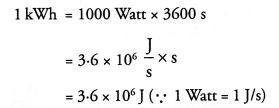
What is the commercial unit of electrical energy ? Represent it in terms of joule.
Answer:
kilowatt hour (kWh) is the commercial unit of electrical energy.
Question 26.
A current of 1 ampere flows in a series circuit containing an electric lamp and a conductor of 5Ω when connected to a 10V battery. Calculate the resistance of the electric lamp.
Now if a resistance of 10Ω is connected in parallel with this series combination, what change (if any) in current flowing through 5Ω condcutor and potentional difference across the lamp will take place ? Give reason. Draw circuit diagram.
(CBSE 2010)
Answer:
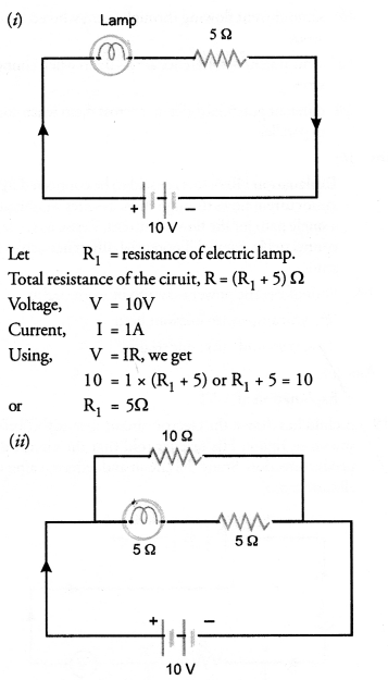
Net resistance of lamp and conductor connected in series = 5 + 5 = 10Ω
Net resistance of the combination oflamp and conductor and resistance 10Ω connected in parallel,
It means 1A current will flow through 10Ω resistance and 1A current will flow through the lamp and conductor of 5Ω resistance. Hence, there is no change in the current through 5Ω conductor.
Now potential difference across the lamp in case (i)
V = IR = 1 x 5 = 5V
Potential difference across the lamp in case (ii)
V = IR = 1 x 5 = 5V
Hence, there is no change in the potential difference across the lamp.
Question 27.
Why is parallel arrangement used in domestic wiring ?
(CBSE 2012)
Answer:
- If any one of the electric devices in parallel fuses, then the working of other devices will not be affected.
- When different devices are connected in parallel, they draw the current as per their requirement and hence they work properly.
Question 28.
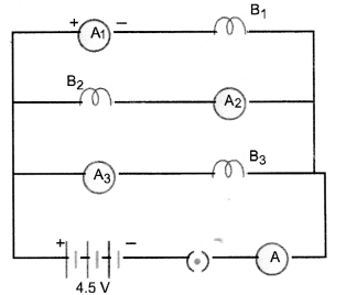
B1, B2 and B3 are three identical bulbs connected as shown in figure. When all the three bulbs glow, a current of 3A is recorded by the ammeter A.
- What happenes to the glow of other bulbs when the bulb B1 gets fused ?
- What happens to the reading of A1, A2, A3 and A when the bulb B2 gets fused ?
- How much power is dissipated in the circuit when all the three bulbs glow together ?
Answer:
- The glow of bulb depends upon the energy disspated per second i.e. P =V2/R.
Since V and R of both the bulbs B2 and B3 remain the same even if bulb B, gets fused so glow of B2 and B3 remain the same. - Since bulbs are identical, so their resistance is equal (i.e. resistance of each bulb = R ohm).
When all bulbs glow, net resistnace of the circuit is given by
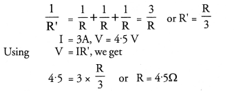
When B2 gets fused, only two bulbs B1 and B2 in parallel are in the circuit.
.’. Net resistance of the circuit is given by
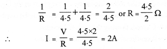
Thus, reading of ammeter A = 2A
Since B1 and B3 are in parallel and have same resistance, so 2A current will be equally distributed between B1 and B3. Therefore, reading of ammeter A1 = 1A Reading of ammeter A3 = 1A Circuit containing B2 is broken, so no current flows through this circuit. Hence reading of ammeter A2 = zero. - Power dissipated in the circuit,
P =V x I
= 4.5 x 3 = 13.5 W
Question 29.
Three incandescent bulbs of 100W each are connected in series in an electric circuit. In another circuit, another set of three bulbs of the same voltage are connected in parallel to the same source.
(a) Will the bulb in the two circuits glow with the same brightness ? Justify your answer.
(b) Now let one bulb in both the circuits get fused. Will the rest of the bulbs continue to glow in each circuit ? Give reason.
(CBSE 2012)
Answer:
(a) Power dissipated in a circuit = V2/R. Since resistance of the circuit containing bulbs connected in series is more than the resistnace of the circuit containing bulbs in parallel, therefore, power dissipated in parallel combination is more than that in series combination. Hence, bulbs connected in parallel will glow more brightly.
(b) In series combination, there is only one path for the flow of current. So when one bulb gets fused, circuit is broken and hence the bulbs stop glowing.
In parallel combination, each bulb has its own path for the flow of current. So when one bulb gets fused, other bulbs will continue to glow as the current is flowing in the circuits of these bulbs.
Question 30.
State Ohms law. How can it be verified experimentally ? Does it hold good under all conditions ? Comment.
(CBSE 2010)
Answer:
For Ohm’s law: Ohm’s law states that the electric current flowing through a conductor is directly proportional to the potential difference across the ends of the conductor, provided the temperature and . other physical conditions of the conductor remain the same.
For experimental verification: Verify Ohm’s law
Apparatus : A conductor of resistance R, an ammeter, a voltmeter, a battery, a variable resistance (or rheostat used to change the current in the circuit), connecting wires, a key and sand paper.
Procedure:
-
- Connect the various components as shown in figure 12.
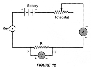
- Close the key, so that current begins to flow in the circuit.
- Note down the potential difference (V) across the conductor PQ of resistance R shown by the voltmeter and the corresponding current (I) shown by the ammeter.
- Now move the knob of rheostat so that the current in the circuit increases.
- Again note down the potential difference (V) across the conductor PQ of resistance R in the voltmeter and current in the circuit shown by ammeter.
- Repeat the experiment at least five times by increasing the current in the circuit by moving the knob of the rheostat in steps.
- Connect the various components as shown in figure 12.
Observations:
|
S.No |
Potential Difference (V) |
Current (I) |
V/I |
|
1. |
|||
|
2. |
|||
|
3. |
|||
|
4. |
|||
|
5. |
|||
|
6. |
|||
|
7. |
Plot a graph between V and I by taking V along X-axis and I along Y-axis. We get a straight line passing through origin as shown in figure 11.
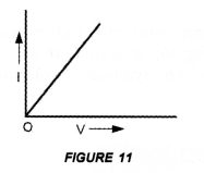
Conclusion: From the graph between V and I, we conclude that I x V, which is Ohm’s law. Hence Ohm’s law is verified experimentally.
Precautions: While verifying Ohm’s law experimentally, the following precautions should be taken :
- Current should not be allowed to pass through the circuit continuously for a long time, which may cause the increase in temperature of the conductor. Therefore, the plug of the key must be taken out every time after noting the readings of ammeter and voltmeter.
- Connections should be tight.
- The conductor used in the experiment should be such that its resistance is not changed with increase in temperature of the conductor.
Ohm’s law holds good if the temperature of the conductor remains the same.
Question 31.
What is electrical resistivity of a material ? What is its unit ?
Describe an experiment to study the factors on which the resistance of conducting wire depends. (CBSE 2012)
Answer:
For Electrical resistivity: Electrical resistivity of a material is defined as the resistance of an object (made of the material) of unit length and unit area of cross-section.
Unit of electrical resistivity is ohm-metre.
For experiment:
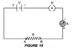
Connect the various electrical components as shown in figure 15.
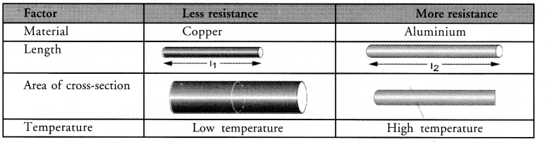
- Dependence of length of a conductor:
Take a copper wire of length l and connect it between the terminals A and B. Note the reading of ammeter. Now take another copper wire of same area of cross-section but of length 2l. Connect it between the terminals A and B by disconnecting the previous wire. Again, note the reading of ammeter. It will be found that the reading of ammeter (i.e., electric current) in the second case is half of the reading of ammeter in the first case. Since R = V/I, so resistance of second wire is double than the resistance of the first wire. Thus, resistance of a conductor is directly proportional to the length of the conductor,
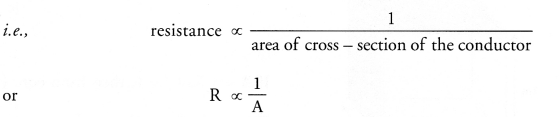
i.e resistance ∝ length of the conductor
Thus, more is the length of a conductor, more is its resistance.
Thus, the resistance of’a conductor is ‘inversely proportional to the area of cross -section of the conductor. - Dependence on area of cross-section of a conductor:
Now take two copper wires of same length but of different area of cross-sections. Let area of cross-section of first wire is more than the area of cross-section of the second wire. Connect first wire between the terminals A and B in the circuit shown in figure 15. Note the reading of ammeter. Now disconnect the first wire and connect the second wire between the terminals A and B. Again note the reading of the ammeter. It will be found that the reading of ammeter (i.e. electric current) is more when first wire (i.e. thick wire) is connected between A and B than the reading of the ammeter when second wire (i.e. thin wire) is connected between the terminals A and B.
Thus, the resistance of a thin wire is more than the resistance of a thick wire. - Effect of the Nature of material:
Take two identical wires, one of copper and other of aluminium. Connect the copper wire between the terminals A and B. Note the reading of ammeter. Now, connect the aluminium wire between the terminals A and B. Again note the reading of ammeter. It is found that the reading of ammeter when copper wire is connected in the circuit is more than the reading of the ammeter when aluminium wire is connected in the circuit.
Therefore, resistance of copper wire is less than the resistance of aluminium wire. Hence, resistance of a wire or a conductor depends upon the nature of the material of the conductor. - Effect of temperature of conductor:
If the temperature of a metallic conductor connected in the circuit increases, its resistance increases.
Thus, factors on which resistance of a conductor depends are :- its length,
- its area of cross-section,
- the nature of its material and
- its temperature.
The various factors affecting resistance of a conductor are given in table 1.
Table 1. Factors affecting resistance of a conductor:
Question 32.
How will you infer with the help of an experiment that the same current flows through every part of the circuit containing three resistances in series connected to a battery ?
Answer:
Perform an activity to show that in series combination of resistors, same current flows through each resistor.
- Connect three resistors of resistances R1 = 1Ω, R2 = 2Ω and R3 = 3Ω in series. (C.B.S.E. 2014)
- Connect the series combination of resistors with a battery of 6 V, a plug key K and an ammeter A as shown in figure 17.
- Note the reading of ammeter after plugging the key. Let it be I.
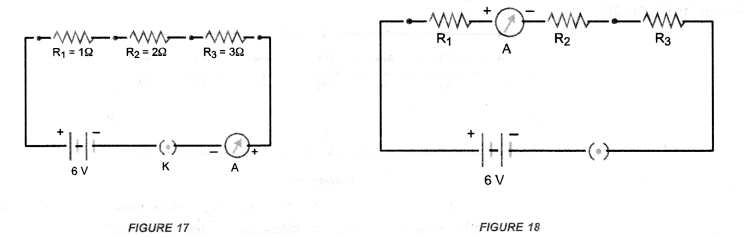
- Now disconnect ammeter and connect it in between the resistors R1 and R2 as shown in figure 18.
- Again plug the key and note the reading of ammeter. It is found that again it is I.
- Now disconnect the ammeter and connect it in between the resistors R2 and R3.
- Plug the key and note the reading of ammeter. Again it is found to be I.
Conclusion : Same amount of current flows through each resistor or element connected in series combination.
Question 33.
How will you conclude that the same potential difference (Voltage) exists across three resistors connected in parallel arrangement to a battery ?
Answer:
Perform an activity to investigate the relation between potential difference across parallel combination of resistors and the potential difference across each individual resistors,
- Connect three resistors of resistances R1, R2 and R3 in parallel. One end of each resistor is joined at a common point ‘a’ and the other end of each resistor is connected at another common point ‘b’.
- Connect the parallel combination of resistors with a battery, a plug key K and an ammeter A as shown in figure 22(A).
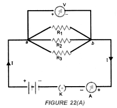
- Now connect a voltmeter across the parallel combination of resistors between a and b points.
- Note the reading of voltmeter. Let it be V. This is the potential difference across the parallel combination of resistors.
- Now, disconnect the voltmeter and connect it across R1 as shown in figure 22(B).
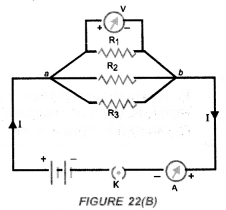
- Note the reading of voltmeter. It is found to be V.
- Disconnect the voltmeter and connect it across R2. Note the reading of voltmeter. It is found to be V.
- Again disconnect the voltmeter and connect it across R3. Note the reading of voltmeter. It is found to be V.
Conclusion : When resistors are connected in parallel to each other, potential difference across each resistor is equal to the potential difference across the parallel combination of resistors.
Question 34.
What is Joule’s heating effect ? How can it be demonstrated experimentally ? List its four applications in daily life.
(CBSE 2012)
Answer:
Joule’s law can be stated as : The amount of heat produced in a conductor is
(i) directly proportional to the square of the electric current flowing through it.
This is H ∝ I2 –
(ii) directly proportional to the resistance of the conductor or resistor.
That is, H ∝ R ‘
(iii) directly proportional to the time for which the electric current flows through the conductor or resistor.
That is, H ∝ t
Combining (i), (ii) and (iii), we get H ∝ I2 Rt.
or H = KI2Rt, where K is constant of proportionality
If K = 1, then H = I2Rt joule
This is known as Joule’s law of heating.
Four Applications:
- When electric appliances like electric heater, electric iron and water heater etc. are connected to the main supply of electricity, these appliances become hot but the connecting wires remain cold.
We know, heat produced is directly proportional to the resistance of the material through which current flows. The element of electric heater is made of nichrome. Since, resistance of nichrome is high, so a large amount of heat is produced in the element of the electric heater. Thus, filament of electric heater becomes red hot. However, heat produced in connecting wires made of copper or aluminium is very small and hence they are not heated up.
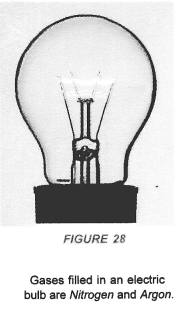
- Filament of an electric bulb is made of a thin wire of tungsten. The melting point of filament is high i.e., about 3380 °C. The filament of the bulb is enclosed in a glass envelope fixed over an insulated support as shown in figure 28. The glass envelope of electric bulb is filled with inactive gases like nitrogen and argon to increase the life of the tungsten filament.
Since resistance of thin filament is very high, so a large heat is produced as the electric current flows through the filament. Due to this large amount of heat produced, filament of the bulb becomes white hot. Hence, the filament of the bulb emits light and heat.
- Electric fuse is a safety device connected in series with the electric circuit. Electric fuse is a wire made of a material whose melting point is very low. Examples of the materials of making fuse wire are copper or tin-lead alloy. When large current flows through a circuit and hence through a fuse wire, a large amount of heat is produced. Due to this large amount of heat, the fuse wire melts and the circuit is broken so that current stops flowing in the circuit. This saves the electric circuit from burning due to the passage of large current through it.
Question 35.
Find out the following in the circuit given in the figure.
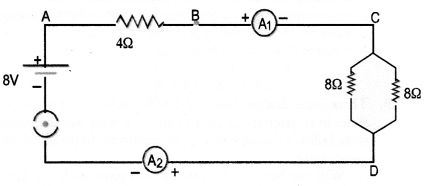
(a) Effective resistance of two 8Ω resistors in the combination.
(b) Current flowing through 40 resistor
(c) Potentional difference across 40 resistor
(d) Power dissipated in 4Ω resistor
(e) Difference in ammeter readings, if any.
(CBSE 2010,2012)
Answer:
(a) Two 80 resistors are in parallel, so their effective resistance is given by
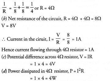
(e) Since same current flows through every part in a series circuit and both the ammeters are connected in series, so there will be no difference in ammeter readings.
Hope given NCERT Exemplar Solutions for Class 10 Science Chapter 12 Electricity are helpful to complete your science homework.
If you have any doubts, please comment below. Learn Insta try to provide online science tutoring for you.