Electromagnetic Waves Class 12 Notes Physics Chapter 8

By going through these CBSE Class 12 Physics Notes Chapter 8 Electromagnetic Waves, students can recall all the concepts quickly.

Electromagnetic Waves Notes Class 12 Physics Chapter 8

→ Displacement current is a 1 ways equal to charging (for discharging) current and lasts so long as the capacitor (producing varying electric field) is charged or discharged.

→ An accelerated charged particle emits e.m. waves.

→ \(\overrightarrow{\mathrm{S}}\) = \(\overrightarrow{\mathrm{E}}\) × \(\overrightarrow{\mathrm{B}}\) is called Poynting vector acts in a direction perpendicular to the plane of \(\overrightarrow{\mathrm{E}}\) and \(\overrightarrow{\mathrm{B}}\) .

→ The displacement current is named so because it is produced by the displacement of electrons caused by changing electric fields.

→ X-rays have the shortest wavelength (≈ 1 Å).

→ The charging or discharging current is called conduction current.

→ The amplitude of electric and magnetic fields in free space in e.m. waves are related as E = CB

→ Electric vector is called light vector as it is responsible for the optical effect of e.m. wave.

→ The energy of the e.m. wave is shared equally between the electric field vector and the magnetic field vector.

→ Microwaves are very commonly used in radar to locate flying objects like airplanes, jet planes, etc.

→ Tire earth’s atmosphere produces Green House effect. In the absence of the earth’s atmosphere, the temperature on earth during the day will increase and during the night it would decrease.

→ The ozone layer which is present in the stratosphere protects the earth from high-energy radiations coming from outer space.

→ The velocity of em. waves in a medium is given by
v = \(\frac{1}{\sqrt{\mu_{0} \varepsilon_{0} \mu_{\mathrm{r}} \varepsilon_{\mathrm{r}}}}=\frac{C}{\sqrt{\mu_{\mathrm{r}} \varepsilon_{\mathrm{r}}}}\)

→ There is no conduction current in a traveling e.m. wave.

→ Earth’s atmosphere is transparent to visible light and most of the infrared rays are absorbed by the atmosphere.

→ Radio waves were discovered by Hertz and are used in communication.

→ e.m. waves are transverse in nature.

→ e.m. waves exert pressure on the objects on which they fall as they carry energy and momentum.

→ The wavelength range of em. waves are from 10-15 m to 109 m and the frequency range is 1024 Hz to 1 Hz.

→ Green House Effect takes place due to the heating of the earth’s atmosphere due to the trapping of infrared rays by the CO2 layer in the atmosphere.

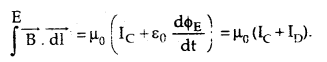
→ Modified Ampere Circuital law: It states that the line integral of the magnetic field around a closed path is always equal to μ0 times the sum of the conduction dnd displacement currents i.e.,
Electromagnetic Waves Class 12 Notes Physics 1
→ Displacement Current: It is defined as the current produced in a region where a change of electric flux takes place due to the change in electric field intensity in that region.

Important Formulae

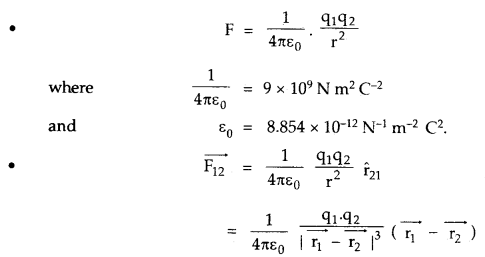
→ Amper’s circuital law states that
∫ \(\overrightarrow{\mathrm{B}}\).\(\overrightarrow{\mathrm{dl}}\) = μ0 IC
where IC = conduction current Displacement current is given by

→ Displacement current is given by
ID = ε0 \(\frac{\mathrm{d} \phi_{\mathrm{E}}}{\mathrm{dt}}\)

→ C = \(\frac{E_{0}}{B_{0}}=\frac{1}{\sqrt{\mu_{0} \varepsilon_{0}}}\)

→ Energy density of electric field, UE = \(\frac{1}{2}\) ε0 E2

→ Energy density of electric field, UB = \(\frac{\mathrm{B}^{2}}{2 \mu_{0}^{2}}\)

→ Intensity of e.m. wave is given by
I = average energy density × speed of e.m. wave
= \(\frac{1}{2}\) ε0E2 × C = ρ/4πr²

→ \(\overrightarrow{\mathrm{B}}\) at a point between the plates of the capacitor at a distance r from its axis is given by.
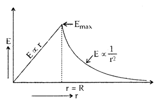
B = \(\frac{\mu_{0} \mathrm{Ir}}{2 \pi \mathrm{R}^{2}}\)
Where R = radius of each circular plate of the capacitor.

→ Velocity of e.m. waves is
C = vλ

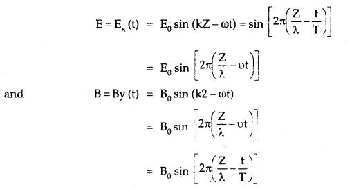
→ An electromagnetic wave of frequency v, wavelength λ propagating along the z-axis, we have
Electromagnetic Waves Class 12 Notes Physics 2
→ The speed of light or of electromagnetic waves in a material medium is given by
υ = \(\frac{1}{\sqrt{\mu \varepsilon}}\)
where μ is the permeability of the medium and ε is its permittivity.

→ Bmax = \(\frac{\mu_{0} I_{D}}{2 \pi R}\)

Alternating Current Class 12 Notes Physics Chapter 7

By going through these CBSE Class 12 Physics Notes Chapter 7 Alternating Current, students can recall all the concepts quickly.

Alternating Current Notes Class 12 Physics Chapter 7

→ In a pure ohmic resistance both alternating current and e.m.f. are in the same phase.

→ Alternating e.m.f. leads the alternating current by \(\frac{π}{2}\) in a pure inductance.

→ In a pure capacitor circuit, the alternating e.m.f. lags behind the alternating current by \(\frac{π}{2}\).

→ xL = ωL is called inductive reactance.

→ xC = \(\frac{1}{\omega C}\) is called capacitance reactance.

→ Resistance, reactance, and impedance all are measured in ohm.

→ The graph between xL and ω is a straight line.

→ The applied voltage is equal to the potential drop across the resistance R at the resonant frequency in the LCR circuit.

→ Power is dissipated only due to the ohmic resistance in an a.c. circuit.

→ Thus in an RC or RL a.c. the circuit power is dissipated only due to R and not due to its inductance or capacitance.

→ Resonant angular frequency is the same both for the series and parallel resonant circuit.

→ The graph between xC and w is a hyperbola.

→ The maximum value of current is I = \(\frac{E_{\mathrm{rms}}}{\mathrm{R}}\)at the resonant angular frequency W = W0.

→ As ω to increases, Z of parallel LCR resonant circuit first increases becomes maximum and then decreases.

→ For series LCR resonant circuit, Z first decreases become minimum and then increases.

→ The power rating of an element used in a.c. circuit refers to its average power rating.

→ The power consumed in an a.c. the circuit is never negative.

→ For very high frequency of a.c., the inductor behaves as an open circuit and the capacitor behaves as a conductor.

→ The impedance of the LR circuit depends upon the frequency of a.c. The phase angle between E and I in an LR circuit also depends upon the frequency.

→ As the frequency of a.e. increases, the impedance of the CR circuit decreases.

→ Electrical resonance takes place when the amplitude of the current in the circuit is maximum and impedance is minimum and the LCR circuit is a purely resistive circuit.

→ For purely resistive circuit, power factor = 1.

→ For purely inductive and capacitive circuits, the power factor is zero. Choke coil is used to control a.c. without much loss of electric power.

→ K > 1 for step-up transformer and K < 1 for step down transformer. Transformer works on the principle of mutual inductance. q = 100% and Eplp = EsIs for an ideal transformer.

→ The power consumed in a circuit is never negative.

→ A.C.: It is defined as the? electric current magnitude of which changes with time and reverses its direction periodically.

→ Average or Mean Value of A.C.: It is defined as that steady current which when passed through a circuit for a half time period of A.C. produces the same amount of charge as is being produced by A.C. in the same time and in the same circuit.

→ R.M.S. value or effective value of A.C.: It is defined as that steady current that produces the same amount of heat in resistance in a given time as is being done by a.c. passed through the same circuit for the same time.

→ Inductive reactance: It is the effective opposition offered by the inductor to the flow of a.c. in the circuit.

→ Capacitive reactance: -It is the effective opposition offered by the capacitor to the flow of a.c. in the circuit.

→ Q-factor of series LCR circuit: It is defined as the ratio of the voltage drop across inductor (or capacitor) to the applied voltage.

→ Power of an a.c. circuit: It is the product of instantaneous e.m.f. and instantaneous current in the circuit.

→ Power factor: It is defined as the ratio of average power to the apparent power.

→ Idle or wattless current: It is the current due to the flow of which no power is consumed in an a.c. circuit.

→ Transformer’s a device used to convert low alternating voltage at high current into a high voltage at low current or vice-versa.

Important Formulae

→ Erms = \(\frac{1}{\sqrt{2}}\) E0 = E virtual = Eeff

→ Irms = \(\frac{1}{\sqrt{2}}\) I0

→ Instantaneous e.m.f. is given by E = E0 sin ωt

→ In a purely inductive circuit, current lags behind E by \(\frac{π}{2}\)
I = I0 sin (ωt – \(\frac{π}{2}\))

→ In a purely capacitive circuit
I = I0 sin (ωt + \(\frac{π}{2}\))

→ XL = ωL = 2πvL = \(\frac{\mathrm{E}_{0}}{\mathrm{I}_{0}}=\frac{\mathrm{E}_{\mathrm{v}}}{\mathrm{F}_{v}}\)

→ XL = \(\frac{1}{\omega C}=\frac{1}{2 \pi v C}=\frac{E_{0}}{I_{0}}=\frac{E_{v}}{I_{v}}\)

→ Average value of induced a.c. over a complete cycle is:
Alternating Current Class 12 Notes Physics 1
→ Average power = apparent power × power factor
or
Pav = Ev Iv cos Φ.

→ cos Φ = \(\frac{\mathrm{R}}{\mathrm{Z}}\)
Alternating Current Class 12 Notes Physics 2
→ Resonant angular frequency of LCR series circuit is given by
ω0 = \(\frac{1}{\sqrt{\mathrm{LC}}}\)
or
v0 = \(\frac{1}{2 \pi \sqrt{L C}}\)

→ Impedence of LCR series circuit is given by
Z = \(\sqrt{R^{2}+\left(X_{L}-X_{C}\right)^{2}}\)
= \(\sqrt{R^{2}+\left(\omega L-\frac{1}{\omega C}\right)^{2}}\)

→ Tangent of the phase angle is given by .
tan Φ = \(\frac{X_{L}-X_{C}}{R}\)

→ Power factor of LR circuit is given by
cos Φ = \(\frac{R}{Z}=\frac{R}{\sqrt{R^{2}+X_{L}^{2}}}\)
tan Φ = \(\frac{\mathrm{x}_{\mathrm{L}}}{\mathrm{R}}=\frac{\omega \mathrm{L}}{\mathrm{R}}\)
Alternating Current Class 12 Notes Physics 3
→ For CR. circuit,
tan Φ = \(\frac{X_{C}}{R}=\frac{1}{R \omega C}\)
Z = \(\sqrt{R^{2}+X_{c}^{2}}=\sqrt{R^{2}+\left(\frac{1}{\omega C}\right)^{2}}\)

→ For a transformer,
K = \(\frac{\mathrm{N}_{\mathrm{s}}}{\mathrm{N}_{\mathrm{p}}}=\frac{\phi_{\mathrm{s}}}{\dot{\phi}_{\mathrm{p}}}=\frac{\mathrm{E}_{\mathrm{s}}}{\mathrm{E}_{\mathrm{p}}}=\frac{\mathrm{I}_{\mathrm{p}}}{\mathrm{I}_{\mathrm{s}}}\)

→ For an ideal transformer,
Alternating Current Class 12 Notes Physics 4
When Zp and Zs are called impedance of primary and secondary coil of the transformer.

→ Efficiency of a transformer is given by,
η = \(\frac{\text { output power }}{\text { input power }}\)
= \(\frac{\mathrm{E}_{\mathrm{s}} \mathrm{I}_{\mathrm{s}}}{\mathrm{E}_{\mathrm{p}} \mathrm{I}_{\mathrm{p}}}\).

→ Maximum e.m.f. induced in a coil is given by e0 = NBAω.
where N = No. of turns of the coil.
A = Area of the coil.
ω = angular frequency of rotation of the coil.
B = magnetic field.

→ Q.factor = \(\frac{\mathrm{X}_{\mathrm{L}} \mathrm{I}}{\mathrm{RI}}=\frac{\omega_{0} \mathrm{~L}}{\mathrm{R}}=\frac{1}{\omega_{0} \mathrm{CR}}=\frac{1}{\mathrm{R}} \sqrt{\frac{\mathrm{L}}{\mathrm{C}}}\)

Electromagnetic Induction Class 12 Notes Physics Chapter 6

By going through these CBSE Class 12 Physics Notes Chapter 6 Electromagnetic Induction, students can recall all the concepts quickly.

Electromagnetic Induction Notes Class 12 Physics Chapter 6

→ An induced e.m.f. is produced in a conductor when it moves through a magnetic field.

→ The induced e.m.f. may also be produced when a stationary conductor is placed in a changing magnetic field.

→ Lenz’s law explains the cause of induced e.m.f.

→ Electromagnetic induction (E.M.L) converts mechanical energy into electrical energy.

→ inductance in the electrical circuit is equivalent to the inertia or mass in mechanics.

→ The dimensional formula of inductance is [ML2 T-2 A-2].

→ The magnetic flux is a scalar quantity and has the dimensions of [ML2 T-2 A-1].

→ The inductance of a coil depends on the

  1. across of cross-section of the coil.
  2. no. of turns in the coil.
  3. permeability of the core of the coil.

→ The direction of induced current can be obtained by Fleming’s right rule.

→ When the magnetic flux through a circuit changes, an induced e.m.f. is produced in it and it lasts so long as the change in the magnetic flux takes place.

→ Eddy currents are set up in any conducting material placed in a varying magnetic field.

→ Eddy currents produce heat at the cost of electrical power and thus reduce power efficiency.

→ Eddy currents can be minimized by using eddy currents.

→ S.I. unit of Φ is weber (Wb).
I Wb = Tm2 = 1 Tesla × 1 m2.

→ S.L. unit of L and M is henry (H).

→ 1 H = 1 VA-1 s.

→ The mutual inductance of two coils depends upon the shape, size, or geometry of two coils and the no. of turns in the two coils.

→ The area of cross-section and length of two coils affect the ‘M’ between two coils.

→ No current flows in a rectangular closed loop moving horizontally in a uniform magnetic field as long as the loop is completely in the magnetic field.

→ Eddy currents don’t cause sparks.

→ Faraday’s flux rule: It states that the induced e.m.f. produced in a closed circuit is directly proportional to the rate of change of the magnetic flux linked with it.
i.e., e ∝ \(\frac{\mathrm{d} \phi}{\mathrm{d} \mathrm{t}}\)
or
e = – \(\frac{\mathrm{d} \phi}{\mathrm{d} \mathrm{t}}\)
when – ve sign shows that ‘e’ acts in a direction opposite to the direction of change in magnetic flux.

→ Lenz’s law: It states that the induced e.m.f. always acts in such a direction so as to opposite the very cause producing it.

→ Self-induction: It is defined as the property of an electrical circuit due to which it opposes the change in the current in the circuit.

→ Self-inductance of a coil: 11 is defined as the magnetic flux linked with a coil when unit current flows through it. It is also equal to the induced e.m.f. produced in the coil when the rate of change of current is unity through it.

→ Mutual inductance of two coils: It is the property of producing induced e.m.f. in a coil by changing the current or magnetic flux linked with the neighboring coil.

→ Coefficient of Mutual induction: It is equal to induced e.m.f. of one coil when the rate of change of current is unity in the neighboring coil.

Important Formulae

→ Φ = \(\overrightarrow{\mathrm{B}}\) . \(\overrightarrow{\mathrm{A}}\) = BA cos θ
where Φ = magnetic flux,
\(\overrightarrow{\mathrm{A}}\) = surface area,
\(\overrightarrow{\mathrm{B}}\) = magnetic field.

→ E or e = – \(\frac{\mathrm{d} \phi}{\mathrm{dt}}\) for one turn and e – \(\frac{\mathrm{Nd} \phi}{\mathrm{dt}}\) for N. turn of a coil.

→ Induced current is given by
I = \(\frac{\mathrm{e}}{\mathrm{R}}=-\frac{\mathrm{N}}{\mathrm{R}} \cdot \frac{\mathrm{d} \phi}{\mathrm{dt}}\)

→ When the magnetic field is parallel to the outward normal to the surface of the coil, then the change in the magnetic flux due to change in field is:
dΦ = Φ2 – Φ1 = B2A – B1A = (B2 – B1)A

→ Charge induced in a circuit is
q = \(\frac{\mathrm{d} \phi}{\mathrm{R}}=\frac{\text { Change in magnetic flux }}{\text { Resistance of circuit }}\)

→ Motional e.m.f. is: e = Blυ.

→ Induced current produced = Blυ/R

→ ε = – L \(\frac{\mathrm{dI}}{\mathrm{dt}}\); L = Self-inductance

→ Force required to pull a rod out of magnetic field is
F = \(\frac{B^{2} l^{2} v}{R}\)

→ e = – M\(\frac{\mathrm{dI}}{\mathrm{dt}}\), M = Mutual inductance.

→ Induced e.m.f. in a coil rotating with angular speed ω in a magnetic field B is e = NBA ω sin ωt. .
e0 = NBAω = max. e.m.f. induced.

→ Self inductance of a long solenoid is given by
L = μ0 n2 Al = \(\frac{\mu_{0} \mathrm{~N}^{2} \mathrm{~A}}{l}\)

→ Mutual inductance of two coils is given by
M = μ0 n1 n2 Al
= \(\frac{\mu_{0} \mathrm{~N}_{1} \mathrm{~N}_{2} \mathrm{~A}}{l}\)
where l = length of primary coil.
A = Area of a cross-section of each coil.

→ The inductance of coils in series is given by
L = L1 + L2 + L3 + …………

→ The inductance of coils in parallel is given by
\(\frac{1}{L_{P}}=\frac{1}{L_{1}}+\frac{1}{L_{2}}+\frac{1}{L_{3}}+\ldots\)

→ Induced charge in terms of B is given by:
q = \(\frac{\mathrm{NBA}}{\mathrm{R}}\)

→ Induced current is given by
I = \(\frac{\mathrm{NA}}{\mathrm{R}}\)(B1 – B2)

→ Also induced charge is given by
q = It = \(=\frac{\mathrm{e}}{\mathrm{R}}\) t

→ If two coils of inductances L1 and L2 are coupled together, then
M = k \(\sqrt{\mathrm{L}_{1} \mathrm{~L}_{2}}\)
where k is called coupling constant,

→ k = 1 for perfectly coupled coils.

→ Two coils are said to be perfectly coupled when the magnetic flux of one coil is completely linked with the second coil.

→ Magnetic energy stored in a coil of inductance L is given by
U = \(\frac{1}{2}\) LI2.

→ ‘e’ produced between the ends of a rod rotating about an end perpendicular to the magnetic field is given by
e= \(\frac{1}{2}\) BWl2 = BA.f, f=frequency.

Magnetism and Matter Class 12 Notes Physics Chapter 5

By going through these CBSE Class 12 Physics Notes Chapter 5 Magnetism and Matter, students can recall all the concepts quickly.

Magnetism and Matter Notes Class 12 Physics Chapter 5

→ Magnetic induction (B) and magnetic intensity (H) are related as B = μH.

→ B is expressed in testa (T) and gauss (G) in S.I. and C.G.S. systems respectively.

→ H in a vacuum is expressed in overstated (C.G.S. system) and Am-1 in S.I. system.

→ The angle of dip at poles is 90° and at the equator, it is zero.

→ S.I. unit of pole strength (m) is NT-1 or Am.

→ The value of angle of dip and declination not only charges from place to place but also at the same place, they change from time to time.

→ Diamagnetism originates from the magnetic moment associated with the orbital motion of electrons.

→ Paramagnetism and Ferromagnetism are associated with the magnetic moment of the spinning electrons.

→ Ferromagnetism depends on temperature. It decreases with an increase in temperature. At a certain temperature called the curie point, the ferromagnetic substance is converted into a paramagnetic substance.

→ The magnetic lines of force always form closed and continuous loops both inside and outside the bar magnet.

→ The magnetic susceptibility of a diamagnetic substance is independent of temperature.

→ The hysteresis cycle for the core of a transformer should be narrow and large in height.

→ The end of the freely suspended magnet pointing towards the north of the earth is called the north pole of the magnet and the end pointing towards the south pole is called the south pole of the magnet.

→ The north and south pole of a magnet is always of equal strength.

→ Monopole never exists.

→ For all purposes, we can consider the magnetic field of a bar magnet and a straight solenoid to be identical.

→ The field inside the solenoid is stronger than the field inside a bar magnet.

→ The earth’s magnetic field at any place is a vector quantity and it requires three parameters to describe it. These are called magnetic elements of the earth.

→ 1 G = 10-4 T.

→ 10 posted = 80 Am-1.

→ The geometric length of a magnet is always more than the magnetic length.

→ A magnetic dipole is the simplest magnetic structure that is known to exist in nature.

→ The strength of the magnetic field of a solenoid can be increased or decreased by adjusting the current and the direction of the magnetic field can be changed by changing the direction of the current.

→ S I. unit of magnetic dipole moment is Joule/tesla (JT-1) or Weber- meter (Wb-m) or Ampere metre2 (Am2).

→ S.I. unit of magnetic flux is weber (Wb).

→ S.I. unit of magnetic permeability (p) is Tm-1 A.

→ Xm has no units.

→ Another S.I. unit of magnetic intensity (H) is N Wb-1.

→ S.I. unit of Intensity of magnetization (I) is Am-1.

→ S.I. unit of Torque and P.E. is Joule (J).

→ S.I. unit of energy dissipated in hysteresis loop is J m-3 cycle-1.

→ B is also called magnetic flux density and has an S.I. unit in Tesla (T).

→ The unit pole is defined as one which when placed in vacuum at a distance of 1 m from an equal and similar pole exerts a force of \(\frac{\mu_{0}}{4 \pi}\) or 10-7 N on it.

→ Magnetic elements: They are the physical quantities that are required to completely specify the earth’s magnetic field at a point, e.g., dip, declination, and BH.

→ Declination at a place: It is defined as the angle between geographical and magnetic meridian at that place.

→ Dip at a place: It is defined as the angle made by the resultant earth’s magnetic field with the horizontal direction.

→ The intensity of induced magnetization: It is defined as the magnetic moment developed per unit volume of the magnetic material. Its value depends on the media in which it is magnetized.

→ Magnetic susceptibility of a given material. It is defined as the ratio of the intensity of magnetization and magnetizing field.
i.e., χm = \(\frac{I}{H}\)

→ The intensity of magnetization (I): It is defined as the magnetic moment developed per unit volume when a magnetic substance is subjected to the magnetizing field.
i.e., I = \(\frac{\mathrm{M}}{\mathrm{V}}=\frac{\mathrm{m} \cdot 2 l}{\mathrm{a} \cdot \mathrm{zl}}=\frac{\mathrm{m}}{\mathrm{a}}\)

→ I is also defined as the pole strength developed per unit area of cross-section of the specimen.

→ Magnetic Induction (B): It is defined as the total no. of magnetic lines of induction (magnetic field lines inside the material) crossing per unit area normally through the magnetic substance.

→ Magnetic permeability (μ): It is the ratio of magnetic induction to the magnetic intensity,
i.e., μ = \(\frac{B}{H}\)

→ Curie’s law: States that the magnetic susceptibility of a paramagnetic material is inversely proportional to its absolute temperature.

→ Curie point: It is defined as the temperature at which a ferromagnetic substance starts behaving as a paramagnetic substance. It is also called Curie temperature.

→ Hysteresis: It is the lag of intensity of magnetization behind the magnetizing field during the magnetization and demagnetization of the ferromagnetic substance.

→ Coercivity and retentivity are also associated with the hysteresis loop.

→ Coulomb’s law of magnetic force: It states that
F ∝ \(\frac{m_{1} m_{2}}{r^{2}}\)
or
F = \(\frac{\mu_{0}}{4 \pi} \cdot \frac{m_{1} m_{2}}{r^{2}}\)

Important Formulae

→ Torque experienced by a magnet or a magnetic dipole in a uniform magnetic field is
τ = | \(\overrightarrow{\mathrm{M}}\) × \(\overrightarrow{\mathrm{B}}\) | = MB sin θ

→ M = magnetic moment, B = magnetic field, θ = angle between \(\overrightarrow{\mathrm{M}}\) and \(\overrightarrow{\mathrm{B}}\).

→ Magnetic dipole moment due to current loop is:
M = nIA
where n = no. of turns in it, I = current, A = area of loop.

→ Work done in rotating a magnet placed in a magnetic field from θ1 to θ2 is
W = MB (cos θ1 – cos θ2)

→ Gauss’s law of magnetism states that
s \(\overrightarrow{\mathrm{B}}\). \(\overrightarrow{\mathrm{dS}}\) = 0

→ Magnetic field due to a magnetic diple at a point on its axis at a distance r from its centre is :
B = \(\frac{\mu_{0}}{4 \pi} \cdot \frac{2 \mathrm{M}}{\mathrm{r}^{3}}\)

→ On equitorial line
B = \(\frac{\mu_{0}}{4 \pi} \cdot \frac{\mathrm{M}}{\mathrm{r}^{3}}\)

→ If the magnet is not short, then
B = \(\frac{\mu_{0}}{4 \pi} \cdot \frac{2 \mathrm{Mr}}{\left(\mathrm{r}^{2}-l^{2}\right)}\) on axial line

→ B equitorial = \(\frac{\mu_{0}}{4 \pi} \cdot \frac{\mathrm{M}}{\left(\mathrm{r}^{2}+l^{2}\right)^{3 / 2}}\)

→ Time period of an oscillating magnet along earth’s magnetic field is given by –
T = 2π \(\sqrt{\frac{I}{M B_{H}}}\)
when I=M.I.of magnet = m \(\left(\frac{l^{2}+b^{2}}{12}\right)\)

→ Magnetic induction is given by
B = μ0 (H + I)

→ B in vacuum is given by
B = μ0H

→ μ = \(\frac{B}{H}\)

→ χm = \(\frac{I}{H}\)

→ μ = (1 + χm)
or
μ = μ0(1 + χm)

→ I = C\(\frac{H}{T}\)

→ μr = \(\frac{\mu}{\mu_{0}}\)

→ BH = B cos δ

→ Bv = B sin δ

→ tan δ = \(\frac{\mathrm{B}_{\mathrm{v}}}{\mathrm{B}_{\mathrm{H}}}\)
where BH and BV are the horizontal and vertical components of earth’s total magnetic field at a point.
δ = angle of dip at that place

→ B = \(\sqrt{B_{H}^{2}+B_{V}^{2}}\)

→ BH = B magnet at the neutral point.

→ Magnetic field due to a straight current carrying cable at a point at a distance r from it is given by:
B = \(\frac{\mu_{0}}{4 \pi} \cdot \frac{2 I}{r}\)

→ \(\frac{\mathrm{M}_{2}}{\mathrm{M}_{1}}=\frac{\mathrm{T}_{l}^{2}-\mathrm{T}_{1}^{2}}{\left(\mathrm{~T}_{2}^{2}+\mathrm{T}_{1}^{2}\right)}\)
where M1 and M2 are magnetic moments of two magnetic field in the vibration magnetometor stirrup with unlike poles in the same direction having time period of T combination T2
T1 = Time period of the combination of two magnetic having like poles in the same direction.

→ tangent law is
B = BH tan θ
where B and BH are the two mutually perpendicular magnetic fields.
θ = angle made by the magnet with BH.

→ I = k tan θ for tangent galvanometer where K = \(\frac{\mathrm{B}_{\mathrm{H}}}{\mathrm{a}}=\frac{2 \mathrm{rB}_{\mathrm{H}}}{\mu_{0} \mathrm{~N}}\) is the reduction factor.

→ Magnetic field at a point due to a Rowland ring is given by
B = μ0 μr n I
where n = no. of turns per unit length.
I = current in the ring.

Moving Charges and Magnetism Class 12 Notes Physics Chapter 4

By going through these CBSE Class 12 Physics Notes Chapter 4 Moving Charges and Magnetism, students can recall all the concepts quickly.

Moving Charges and Magnetism Notes Class 12 Physics Chapter 4

→ An electric charge at rest produces an electric field around it while a moving charge produces both electric and magnetic fields.

→ A magnet at rest produces a magnetic field around it.

→ An oscillating, as well as an accelerated charge, produces e.m. waves.

→ No poles are produced in a coil carrying current but such a coil shows N and S polarities.

→ 1T = 104 G = 1 Wb m-2 = 104 maxwell cm-2.

→ A current-carrying conductor has a magnetic field and not an electric field around it.

→ Work done in moving a unit pole around a long conductor is
W = μ0 I

→ The torque acting on the loop is independent of its shape but depends on the area of the loop.

→ Path of a charged particle in a magnetic field ( \(\overrightarrow{\mathrm{B}}\) ) is a straight line when it moves parallel or anti-parallel to \(\overrightarrow{\mathrm{B}}\) and is a circle when moves perpendicular to \(\overrightarrow{\mathrm{B}}\)

→ Two parallel conductors with currents in the same direction attract each other which is a magnetic interaction and if the current flows in them in opposite direction, then they repel each other.

→ Magnetic force is always normal to the field.

→ Magnetic force is not a central force.

→ A long straight current-carrying cylinder for an external point behaves like a straight current-carrying wire.

→ If the battery is connected to two points A and B of a conducting ring, the magnetic field at the center due to the current in the ring is zero.
Moving Charges and Magnetism Class 12 Notes Physics 1
→ A long coil of wire is called a solenoid. Its magnetic field is similar to that of the magnet.

→ The electric field is conservative in nature and ∮ \(\overrightarrow{\mathrm{E}}\).\(\overrightarrow{\mathrm{dl}}\)= 0 but the magnetic field is not conservative as ∮ \(\overrightarrow{\mathrm{B}}\). \(\overrightarrow{\mathrm{dl}}\) = μ0 I.

→ The total force on a planar current loop in a magnetic field is always zero.

→ The radius of a charged particle moving in a magnetic field is directly proportional to its momentum.

→ Speed or K.E. of the particle always remains constant in \(\overrightarrow{\mathrm{B}}\) as \(\overrightarrow{\mathrm{F}_{\mathrm{m}}}\) is perpendicular to \(\overrightarrow{\mathrm{B}}\) .

→ The nature of a circular path followed by a charged particle moving in a given magnetic field depends upon the following:

  1. Direction of \(\overrightarrow{\mathrm{B}}\),
  2. The direction of motion of the charged particle,
  3. Nature of charge.

→ For a positively charged particle moving towards RHS in a downward \(\overrightarrow{\mathrm{B}}\), the circular path is anticlockwise and for a negatively charged particle, it is clockwise.

→ The \(\overrightarrow{\mathrm{B}}\) is uniform (except near the ends) for a sufficiently long solenoid and is independent of its length and area of cross-section.

→ Cyclotron cannot be used to accelerate electrons.

→ A galvanometer is a low resistance instrument.

→ It can be converted into an ammeter by connecting a small resistance parallel to it.

→ Ammeter is always connected in series in the circuit.

→ A galvanometer is converted into a voltmeter by connecting a high resistance in series. The voltmeter is always connected in parallel to the circuit.

→ Two parallel streams of protons with protons moving in the same direction repel each other. There is an electric as well as magnetic interaction. The electric interaction gives repulsive force while the magnetic interaction gives an attractive force. As Fe > Fm, so there is a net repulsion between them.

→ When the above raid stream moves in the opposite direction, then they repel each other.

→ Fe and Fm being repulsive, so there is a net repulsive force between them.

→ The minimum potential difference across the terminals of the galvanometer for full-scale deflection is
Vg = Ig G.

→The potential diff. V across the terminals of a combination of R and G is V = Ig (R + G).

→ \(\frac{\mathrm{V}}{\mathrm{V}_{\mathrm{g}}}=\frac{\mathrm{R}-\mathrm{G}}{\mathrm{G}}\) is called voltage multiplying power of series resistance R and denoted as n.
∴ n = \(\frac{V}{V_{g}}=\frac{R+G}{G}\) ⇒ R = G (n – 1).

→ Rv = R + G = nG.

→ Fleming’s left-hand rule helps us to know the direction of the force on a moving charge or on a current-carrying conductor placed in a uniform magnetic field.

→ Current element: It is the product of current and the length of conductor carrying current i.e., current element = I. \(\overrightarrow{\mathrm{l}}\) .It is a vector quantity acting along I.

→ The direction in a magnetic field along which the current-carrying conductor experiences no force is called the direction of the magnetic field.

→ Pitch of the helix (p): It is defined as the distance traveled by the particle along the magnetic field in one revolution i.e., in a time T.
∴ p = υ cos θ × T = υ cos θ. \(\frac{2 \pi m}{B q}=\frac{2 \pi m v \cos \theta}{B q}\)

→ Shunt: It is a small resistance connected in parallel to the galvanometer.

Important Formulae

→ \(\overrightarrow{\mathrm{B}}\) due to a straight current carrying conductor is given by
\(\overrightarrow{\mathrm{B}}\) = \(\frac{\mu_{0} \mathrm{I}}{4 \pi \mathrm{a}}\)(sin Φ1 + sin Φ2)

→ For infinitely long conductor,
\(\overrightarrow{\mathrm{B}}\) = \(\frac{\mu_{0}}{4 \pi} \cdot \frac{2 \mathrm{I}}{\mathrm{a}}\)
where a = perpendicular distance of the point from the conductor
I = current in the conductor

→ \(\overrightarrow{\mathrm{B}}\) at a point on the axis of a current carrying loop of n turns at a distance x from its centre is given by
\(\overrightarrow{\mathrm{B}}\) = \(\frac{\mu_{0} \mathrm{nIR}^{2}}{2\left(\mathrm{x}^{2}+\mathrm{R}^{2}\right)^{\frac{3}{2}}}\)
where R = radius of loop

→ \(\overrightarrow{\mathrm{B}}\) at its centre is given by
B = \(\frac{\mu_{0} \mathrm{nIR}^{2}}{2 \mathrm{R}^{3}}=\frac{\mu_{0} \mathrm{nI}}{2 \mathrm{R}}\)

→ Magnetic field inside a solenoid having n tums/length is given by
B = µ0 nI.

→ \(\overrightarrow{\mathrm{B}}\) at a point near its end is given by
B = \(\frac{1}{2}\) µ0 nI

→ Maximum energy attained by a particle in a cyclotron is:
Emax = \(\frac{\mathrm{e}^{2} \mathrm{~B}^{2} \mathrm{r}_{\max }^{2}}{2 \mathrm{~m}}\)

→ Potential difference required to accelerate an electron is
V = \(\frac{B^{2} r^{2} e}{2 m}\)

→ Force on a charge moving in \(\overrightarrow{\mathrm{B}}\) is
\(\overrightarrow{\mathrm{F}_{\mathrm{m}}}\) = q(\(\overrightarrow{\mathrm{υ}}\) × \(\overrightarrow{\mathrm{B}}\))
Fmax = qυB

→ Force between two moviiig dia rges s
F = \(\frac{\mu_{0}}{4 \pi} \cdot \frac{\mathrm{q}_{1} \mathrm{q}_{2} v_{1} v_{2}}{\mathrm{r}^{2}}\)

→ Force per unit length between two infinitely long current carrying parallel conductors is
F = \(\frac{\mu_{0}}{4 \pi} \cdot \frac{2 \mathrm{I}_{1} \mathrm{I}_{2}}{\mathrm{r}}\)

→ qυB = \(\frac{\mathrm{m} v^{2}}{\mathrm{r}}\) ⇒ r = \(\frac{\mathrm{m} v}{\mathrm{q} \mathrm{B}}\)

→ Time period, T = \(\frac{2 \pi m}{B q}\)

→ \(\overrightarrow{\mathrm{B}}\) due to current carrying conductor is
B = \(\frac{\mu_{0}}{4 \pi}\).\(\frac{\mathrm{Id} l \sin \theta}{\mathrm{r}^{2}}\)
or
\(\overrightarrow{\mathrm{B}}\) = \(\frac{\mu_{0}}{4 \pi} \cdot \frac{\mathrm{I} \overrightarrow{\mathrm{d} l} \times \hat{\mathrm{r}}}{\mathrm{r}^{2}}=\frac{\mu_{0}}{4 \pi} \cdot \frac{\mathrm{I} \overrightarrow{\mathrm{d} l} \times \overrightarrow{\mathrm{r}}}{\mathrm{r}^{3}}\)

→ G.Ig = (I – Ig)S.⇒ S = \(\frac{\mathrm{I}_{\mathrm{g}} \mathrm{G}}{\mathrm{I}-\mathrm{I}_{\mathrm{g}}}\)

→ V = Ig(G + R).

→ RA = ammeter resistance = \(\frac{\mathrm{GS}}{\mathrm{G}+\mathrm{S}}\)

→ Voltmeter resistance = RV = G + R

→ No. of revolutions per second = \(\frac{\text { speed }}{\text { circumference }}=\frac{v}{2 \pi r}\)

→ I = ne, where n = \(\frac{\mathrm{v}}{2 \pi \mathrm{r}}\)

→ Force on current carrying conductor in a \(\overrightarrow{\mathrm{B}}\) is, F = BIl sin θ

→ Fmax = BIl if θ = 90°.

→ Current sensitivity = \(\frac{\theta}{I}=\frac{N A B}{k}\)

→ Voltage sensitivity = \(\frac{\theta}{\mathrm{V}}=\frac{\theta}{\mathrm{IR}}=\frac{\mathrm{SI}}{\mathrm{R}}=\frac{\mathrm{NAB}}{\mathrm{kR}}\)

→ Torque on a current carrying coil in \(\overrightarrow{\mathrm{B}}\)is τ = nBAI sin θ = nBIA cos α where θ = angle made by \(\overrightarrow{\mathrm{B}}\) with the normal to the plane of coil and
α = angle made by \(\overrightarrow{\mathrm{B}}\) with the plane of coil.

Current Electricity Class 12 Notes Physics Chapter 3

By going through these CBSE Class 12 Physics Notes Chapter 3 Current Electricity, students can recall all the concepts quickly.

Current Electricity Notes Class 12 Physics Chapter 3

→ The time rate of flow of electric charge is called electric constant.

→ S.I. unit an electric current is Ampere (A).
1A = 1 C S-1.

→ Although a direction is associated with the electric current, yet it is a scalar quantity.

→ The current density is a vector quantity directed along the direction of the flow of current.

→ The number density of free electrons is of the order of 1022 per cm3.

→ The number density of free electrons is negligible in insulators.

→ S.I. unit of resistance is the ohm (Ω)

→ The reciprocal of resistance is conductance and has S.I. unit mho or Siemen (S).

→ The conductor is said to be ohmic if they obey Ohm’s law. The V-I graph for such a conductor is a straight line.

→ The conductors are said to be non-ohmic if they don’t obey Ohm’s law. The V-I graph is not a straight line for such conductors.

→ When current is drawn from a cell its terminal potential difference is less than the e.m.f. of the cell.

→ Series combination of cells is used when the internal resistance of the cell is negligible as compared to the external resistance of the circuit.

→ The parallel combination of cells is used when the external resistance of the circuit is much smaller as compared to the internal resistance of the cell

→ The mixed grouping of cells is used when the external resistance of the circuit is of the same order as the internal resistance of the cell i.e., R ≈ r.

→ Wheatstone bridge is a circuit consisting of four resistances P, Q, R, and S a galvanometer and a battery connected such that
\(\frac{P}{Q}=\frac{R}{S}\)

→ It is said to be balanced when there is no current through the galvanometer.

→ Metre bridge or Slide wire bridge is the commonly used form of the wheat stone bridge.

→ The current in the external circuit flows from the + ve to – ve terminal of the cell or battery and is called conventional current which is opposite to the electronic current.

→ Current is the same through the resistors connected in series.

→ The pot. difference is the same through the resistors connected in parallel.

→ 1 A = 6.25 × 10¹⁸ electrons flow per second

→ When a cell is short-circuited, the terminal potential diff. across it is zero.

→ α for most metals is \(\frac{1}{273}\)K-1.

→ a (temperature coefficient of resistance) for insulators and semiconductors is – ve but + ve for metals.

→ The terminal P.D. of a cell depends on the internal resistance (r) of the cell, hence it also depends on the factors on which r depends like, the area of plates, the separation between the plates, cone, electrolyte, nature of electrodes, temperature, etc.

→ 1 KWh = 3.6 × 10⁶ J.

→ Ohm’s law: States that if physical conditions of a conductor like temperature etc. remain unchanged, then the current flowing through it is directly proportional to the potential difference applied across it.

→ Resistance of a conductor is defined as the opposition offered by it to the flow of current. It is equal to the ratio of P.D. (V) and current (I) through the conductor.
i.e, R = \(\frac{V}{I}\)

→ Current density (I): It is defined as the current per unit area of the cross-section of the conductor.
i.e., J = \(\frac{I}{A}\)

→ The internal resistance of a cell: It is defined as the resistance offered by the electrolyte of the cell to the flow of current through it.

→ Conductance: It is defined as the reciprocal of the resistance of the conductor.
i.e., G = \(\frac{1}{R}\)

→ Conductivity: It is defined as reciprocal of the resistivity of the conductor i.e. σ = \(\frac{1}{ρ}\)

→ Temperature coefficient of resistance of a conductor: It is defined as the increase in resistance per unit original resistance at 0°C per unit rise in its temperature.

→ Principle of potentiometer: It states that when a constant current is passed through a conductor of the uniform area of cross-section, the potential drop across any part of it is always directly proportional to the length of that part.
V ∝ l

→ Electric energy: It is defined as the total work done by the source of energy in maintaining the electric current through the circuit for a given time.

→ KWh: The electric energy consumed or dissipated in the circuit is said to be 1 Kilowatt-hour if a device of 1 kW power is used for one hour. It is also called UNIT.

→ Electric power: It is defined as the rate of doing work by the source .of e.m.f. in maintaining the electric current in the circuit.

→ 1 Watt: The electric power of a circuit or a device is said to be 1 watt if one ampere current flows through it on applying a P.D. of one volt.

→ Shunt: It is defined as a small resistance connected in parallel to the cell.

Important Formulae

→ Current density (J) and electric field are related as:
J = σE
R = ρ\(\frac{l}{A}\)
ρ = \(\frac{1}{σ}\)
where ρ = resistivity or specific resistance of the conductor having conductivity σ.

→ internal resistance of the cell is given by
r = \(\left(\frac{E-V}{V}\right)\)R = \(\left(\frac{\mathrm{E}}{\mathrm{V}}-1\right)\)R

→ Using potentiometer r is calculated using
r = \(\left(\frac{l_{1}}{l_{2}}-1\right)\)S = \(\left(\frac{l_{1}-l_{2}}{l_{2}}\right)\)S
where l1 and l2 are balancing lengths with cell in open closed circuits respectively.
S = shunt resistance

→ Drift velocity is given by
υd = \(\frac{\mathrm{I}}{\text { neA }}\)
or
I = neAvd.

→ Current in the serìcs circuit of n cells is
Is = \(\frac{n E}{R+n r}\)

→ Current in the circuit of m cells in parallel is given by
Ip = \(\frac{E}{R+\frac{r}{m}}\)

→ In mixed grouping of cells, I in the circuit is given by,
Im = \(\frac{\mathrm{nE}}{\mathrm{R}+\frac{\mathrm{nr}}{\mathrm{m}}}\)

→ I due to a single cell is
I = \(\frac{E}{R+r}\)

→ The equivalent resistance and power of resistance connected in series are given by:
Rs = R1 + R2 + R3 + ……………
and \(\frac{1}{P_{\mathrm{s}}}=\frac{1}{P_{1}}+\frac{1}{P_{2}}+\frac{1}{P_{3}}+\ldots\)

→ Time required to neutralise earth’s surface,
t = \(\frac{\sigma \mathrm{A}}{\mathrm{I}}=\frac{\sigma .4 \pi \mathrm{R}^{2}}{\mathrm{I}}\)
Where R = radius of earth,
σ = surface charge density
I = current over globe

→ The equivalent resistance and power of resistance connected in parallel are given by and
\(\frac{1}{\mathrm{R}_{\mathrm{P}}}=\frac{1}{\mathrm{R}_{1}}+\frac{1}{\mathrm{R}_{2}}+\frac{1}{\mathrm{R}_{3}}+\ldots\) and
Pp = P1 + P2 + P3 + ………….

→ Electric energy is given by
E = Pt = VIt = I2Rt = \(\frac{\mathrm{V}^{2}}{\mathrm{R}}\) t.

→ Electric power is given by
P = \(\frac{E}{t}\) = VI = I2R = \(\frac{\mathrm{V}^{2}}{\mathrm{R}}\)

→ Variation of resistance and resistivity with temperature is given by
Rt = R0 (1 + α Δ t)
and pt = p0 (1 + αΔt)

→ V = kl for potentiometer.

→ \(\frac{\mathrm{E}_{1}}{\mathrm{E}_{2}}=\frac{l_{1}}{l_{2}}\) where E1 and E2 are emfs of two cells l1, l2 = corresponding balancing lengths.

→ \(\overrightarrow{v_{\mathrm{d}}}\) = – \(\frac{\mathrm{e} \overrightarrow{\mathrm{E}}}{\mathrm{m}}\) τ

→ ρ = \(\frac{\mathrm{m}}{\mathrm{ne}^{2} \tau}\)
where τ = relaxation time,
n = current density of free electron,
e = charge of an electron.

Electrostatic Potential and Capacitance Class 12 Notes Physics Chapter 2

By going through these CBSE Class 12 Physics Notes Chapter 2 Electrostatic Potential and Capacitance, students can recall all the concepts quickly.

Electrostatic Potential and Capacitance Notes Class 12 Physics Chapter 2

→ The S.I. unit of electric potential and a potential difference is volt.

→ 1 V = 1 J C-1.

→ Electric potential due to a + ve source charge is + ve and – ve due to a – ve charge.

→ The change in potential per unit distance is called a potential gradient.

→ The electric potential at a point on the equatorial line of an electric dipole is zero.

→ Potential is the same at every point of the equipotential surface.

→ The electric potential of the earth is arbitrarily assumed to be zero.

→ Electric potential is a scalar quantity.

→ The electric potential inside the charged conductor is the same as that on its surface. This is true irrespective of the shape of the conductor.

→ The surface of a charged conductor is equipotential irrespective of its shape.

→ The potential of a conductor varies directly as the charge on it. i.e., V ∝ \(\frac{l}{A}\)

→ Potential varies inversely as the area of the charged conductor i.e.

→ S.I. unit of capacitance is Farad (F).

→ The aspherical capacitor consists of two concentric spheres.

→ A cylindrical capacitor consists of two co-axial cylinders.

→ Series combination is useful when a single capacitor is not able to tolerate a high potential drop.

→ Work done in moving a test charge around a closed path is always zero.

→ The equivalent capacitance of series combination of n capacitors each of capacitance C is
Cs = \(\frac{C}{n}\)

→ Cs is lesser than the least capacitance in the series combination.

→ The parallel combination is useful when we require large capacitance and a large charge is accumulated on the combination.

→ If two charged conductors are connected to each other, then energy is lost due to sharing of charges, unless initially, both the conductors are at the same potentials.

→ The capacitance of the capacitor increases with the dielectric constant of the medium between the plates.

→ The charge on each capacitor remains the same but the potential difference is different when the capacitors are connected in series.

→ P. D. across each capacitor remains the same but the charge stored across each is different during the parallel combination of capacitors.

→ P.E. of the electric dipole is minimum when θ = 0 and maximum when θ = 180°

→ θ = 0° corresponds to the position of stable equilibrium and θ = π to the position of unstable equilibrium.

→ The energy supplied by a battery to a capacitor is CE2 but energy stored
in the capacitor is \(\frac{1}{2}\) CE2.

→ A suitable material for use as a dielectric in a capacitor must have a high dielectric constant and high dielectric strength.

→ Van-de Graaf generator works on the principle of electrostatic. induction and action of sharp points on a charged conductor.

→ The potential difference between the two points is said to be 1 V if 1 J of work is done in moving 1 C test charge from one point to the another.

→ The electric potential at a point in \(\overrightarrow{\mathrm{E}}\): It is defined as the amount of work done in moving a unit + ve test charge front infinity to that point.

→ Electric potential energy: It is defined as the amount of work is done in bringing the charges constituting a system from infinity to their respective locations.

→ 1 Farad: The capacitance of a capacitor is said to be 1 Farad if 1 C charge given to it raises its potential by 1 V

→ Dielectric: It is defined as an insulator that doesn’t conduct electricity but the induced charges are produced on its faces when placed in a uniform electric field.

→ Dielectric Constant: It is defined as the ratio of the capacitance of the capacitor with a medium between the plates to its capacitance with air between the plates

→ Polarisation: It is defined as the induced dipole moment per unit volume of the dielectric slab.

→ The energy density of the parallel plate capacitor is defined as the energy per unit volume of the capacitor.

→ Electrical Capacitance: It is defined as the ability of the conductor to store electric charge.

Important Formulae

→ Electric potential at a point A is
VA = \(\frac{W_{∞} A}{q_{0}}\)

→ V = \(\frac{1}{4 \pi \varepsilon_{0}}. \frac{q}{r}\)

→ Electric field is related to potential gradient as:
E = – \(\frac{\mathrm{dV}}{\mathrm{dr}}\)

→Electric potential at point on the axial line of an electric dipole is:
V = \(\frac{1}{4 \pi \varepsilon_{0}} \cdot \frac{q}{r^{2}}\)

→ Electric P.E. of a system of point charges is given
υ = \(\frac{1}{4 \pi \varepsilon_{0}} \sum_{i=1}^{n} \sum_{j=1 \atop j \neq i}^{n} \frac{q_{i} a_{j}}{r_{i j}}\)

→ V due to a charged circular ring on its axis is given by:
V = \(\frac{1}{4 \pi \varepsilon_{0}} \cdot \frac{q}{\left(R^{2}+r^{2}\right)^{1 / 2}}\)

→ V at the centre of ring of radius R is given by
V = \(\frac{1}{4 \pi \varepsilon_{0}} \cdot \frac{q}{R}\)

→ The work done in moviag a test large from one point A to another point B having positions vectors \(\overrightarrow{\mathrm{r}_{\mathrm{A}}}\) and \(\overrightarrow{\mathrm{r}_{\mathrm{A}}}\) respectively w.r.t. q is given by
WAB = \(\frac{1}{4 \pi \varepsilon_{0}} \cdot q \cdot\left(\frac{1}{r_{B}}-\frac{1}{r_{A}}\right)\)

→ Line integral of electric field between points A and B is given by.
∫AB \(\overrightarrow{\mathrm{E}}\) \(\overrightarrow{\mathrm{dl}}\) = \(\frac{1}{4 \pi \varepsilon_{0}} \cdot \mathrm{q}\left(\frac{1}{\mathrm{r}_{\mathrm{A}}}-\frac{1}{\mathrm{r}_{\mathrm{B}}}\right)\)

→ Electric potential energy of an electric dipole is
U = – \(\overrightarrow{\mathrm{p}}\). \(\overrightarrow{\mathrm{E}}\)

→ Capacitance of the capacitor is given by
C = \(\frac{q}{V}\)

→ P.E. of a charged capacitor is:
U = \(\frac{1}{2}\) qV = \(\frac{1}{2}\) CV2 = \(\frac{\mathrm{q}^{2}}{2 \mathrm{C}}\)

→ C of a parallel plate capacitor with air between the plates is:
C0 = \(\frac{\varepsilon_{0} \cdot A}{d}\)
C0 = \(\frac{\varepsilon_{0} \mathrm{KA}}{\mathrm{d}}\)

→ C of a parallel plate capacitor with a dielectric medium between the plates is:
C = \(\frac{C_{m}}{C_{0}}=\frac{E_{0}}{E}\)

→ Common potential as
V = \(\frac{C_{1} V_{1}+C_{2} V_{2}}{C_{1}+C_{2}}\)

→ loss of electrical energy = \(\frac{1}{2}\left(\frac{\mathrm{C}_{1} \mathrm{C}_{2}}{\mathrm{C}_{1}+\mathrm{C}_{2}}\right)\left(\mathrm{V}_{1}-\mathrm{V}_{2}\right)\)

→ Energy supplied by battery is CE2 and energy stored in the capacitor is \(\frac{1}{2}\) CE2.

→ The equivalent capacitance of series combination of three capacitor is given by
\(\frac{1}{C_{s}}=\frac{1}{C_{1}}+\frac{1}{C_{2}}+\frac{1}{C_{3}}\)

→ The equivalent capacitance of parallel grouping of three capacitors is
Cp = C1 + C2 + C3

→ Capacitance of spherical capacitor is
C = 4πε0 \(\frac{a b}{b-a}\)
a, b are radii of inner and outer spheres.

→ Capacitance of a cylindrical capacitor is given by:
C = \(\frac{2 \pi \varepsilon_{0}}{\log _{e}\left(\frac{b}{a}\right)}\)
when b, a are radii of outer and inner cylinder.

→ Capacitance of a capacitor in presence of conducting slab between the plates is .
C = \(\frac{\mathrm{C}_{0}}{1-\frac{\mathrm{t}}{\mathrm{d}}}\) = ∞ if t = d.

→Capacitances of a capacitor with a dielectric medium between the plates is given by
C = \(\frac{C_{0}}{\left[1-\frac{t}{d}\left(1-\frac{1}{R}\right)\right]}\)
C = K C0 If t = d

→ Reduced value of electric field in a dielectric slab is given by
E = E0 – \(\frac{P}{\varepsilon_{0}}\)
where P = σp = induced charge density.

→ Capacitance of an isolated sphere is given by
C = 4πε0 r .
C = 4πε0 Kr

Electric Charges and Fields Class 12 Notes Physics Chapter 1

By going through these CBSE Class 12 Physics Notes Chapter 1 Electric Charges and Fields, students can recall all the concepts quickly.

Electric Charges and Fields Notes Class 12 Physics Chapter 1

→ The charge on an electron and proton is called a fundamental charge.

→ Electric charge is quantized and charge on a body can be expressed as, q = ± ne, where n is an integer and e = 1.6 × 10⁻¹⁹ C.

→ The minimum value of the dielectric constant is 1 for free space.

→ The maximum value of the dielectric constant is infinity for conductors i.e., metals.

→ A dielectric constant is a dimensionless number as it is the ratio of two similar quantities.

→ Electric charge is a scalar quantity.

→ Electric charge obeys the law of conservation of charge.

→ It is always additive in nature.

→ Coulomb’s law in vector form is more informative than in its scalar form.

→ The electrostatic force is a central force as it acts along the line joining the centers of two charges.

→ The electrostatic force is Newtonian force i.e., obey’s Newton’s third law of motion.

→ Static electricity or frictional electricity on bodies occurs mainly due to the transfer of electrons from one body to another body.

→ 1 C = 3 × 10⁹ stat Coulomb.

→ Stat Coulomb is the C.G.S. unit of charge. It is also called an electrostatic unit (e.s.u.) of charge.

→ S.I. unit of the electric field is NC-1.

→ The dielectric constant is also known as the relative permittivity of the medium (sr).

→ Two equal and opposite charges separated by a finite distance constitute an electric dipole.

→ S.I. Unit of dipolemoment is Coulomb metre (Cm).

→ Electric dipole moment is a vector quantity acting from – q to + q charge.

→ In a uniform electric field, the net force on the dipole is zero and it experiences a torque only,

→ In a uniform electric field, a dipole has only rotatory motion.

→ In a non-uniform electric field, the dipole experiences both torque and force, hence it has rotatory as well as translatory motion.

→ Electric lines of force never intersect each other. They always leave or enter the surface of the conductor perpendicularly.

→ The electric field inside a charged or uncharged conductor placed in an external field is always zero.

→ Electric flux is a scalar quantity and its S.l. unit is Nm-2 C-1.
The electric field is maximum at the surface of a charged spherical shell and zeroes inside it.

→ The electric field due to a cloud of charge or due to a solid charged sphere is maximum at its surface and varies with distance from its center as:
Electric Charges and Fields Class 12 Notes Physics 1

→ Electric field lines are perpendicular to the equipotential surface.

→ The surface of a charged conductor is an equipotential surface.

→ Coulomb’s law is valid only for point charges.

→ The electric charge does not change with velocity.

→ No point charge produces an electric field at its own location.

→ Electric charge resides only on the outer surface of a conductor.

→ Coulomb’s force between two charges is independent of the presence of other charges.

→ E is independent of the shape of the conductor.

→ E at a point on the surface of a conductor is directly proportional to the surface density of charge at that point.

→ Eat the center of a charged circular ring is always zero.

→ Coulomb’s law in electrostatics: Two-point charges attract or repel each other with a force directly proportional to the product of the magnitude of charges and inversely proportional to the square of the distance between them.

→ Frictional electricity: Electricity produced on bodies when they are rubbed against each other.

→ Additive nature, of charge: Total charge on an isolated system is equal to the algebraic sum of all individual charges of the system.

→ Law of conservation of charge: Total charge on an isolated system always remains conserved.

→ Principle of superposition: It states that the total force on a given point charge due to other interacting charges is the vector sum of the forces applied by the individual charges on it.

→ Test charge: It is a small +ve charge. It is denoted by q0.

→ Electric field: It is defined as the space around a point charge in which its effect can be felt.
Or
It is the limiting value of electrostatic force per unit test charge
Electric Charges and Fields Class 12 Notes Physics 2
→ Electric dipole: It is a system of two equal and opposite charges separated by a finite distance.

→ Electric dipole moment: It is defined as the product of magnitude. of either charge and the dipole length.

→ Electric line of force: It is defined as the path straight or curved tangent at every point of which gives the direction of the electric field.

→ Electric flux (Φ): It is defined as the total number of electric lines of force passing through an area held normal to them around a given point.

→ Gauss’s law or Theorem: It states that the electric flux through a \(\frac{1}{\varepsilon_{0}}\) closed surface is: times the total charge enclosed inside it.
i.e. Φ = ∮\(\overrightarrow{\mathrm{E}} \overrightarrow{\mathrm{dS}}\) = \(\frac{\mathrm{q}}{\varepsilon_{0}}\)

Gaussian Surface: It is defined as any closed surface around the charge distribution enclosing some charge in it.

Important Formulae:
Electric Charges and Fields Class 12 Notes Physics 3
Electric field due to a point charge q is given by
Electric Charges and Fields Class 12 Notes Physics 4

→ The dipole moment of an electric dipole is
\(\overrightarrow{\mathrm{p}}\) = 2 \overrightarrow{\mathrm{a}} q.

→ Electric field at a point on the axis at a distance x from centre of a
charged circular coil of radius r having charge q centre is given by
E = \(\frac{1}{4 \pi \varepsilon_{0}} \frac{q x}{\left(r^{2}-x^{2}\right)^{3 / 2}}\) alongitsaxis.

→ Electric field at a point on the axial line of an electric dipole at a distance r from its centre is given by
E = \(\frac{1}{4 \pi \varepsilon_{0}} \cdot \frac{2 p r}{\left(r^{2}-a^{2}\right)^{2}}\)
= \(\frac{1}{4 \pi \varepsilon_{0}} \cdot \frac{2 p}{r^{3}}\) for a short dipole.

→ Electric field at a point on the equitorial line of an electric dipole at a distance r from its centre is given by
E = \(\frac{1}{4 \pi \varepsilon_{0}} \frac{q x}{\left(r^{2}-x^{2}\right)^{3 / 2}}\)
= \(\frac{1}{4 \pi \varepsilon_{0}} \cdot \frac{p}{r^{3}}\) for a short dipole.

→ Torque on an electric dipole in a uniform \(\overrightarrow{\mathrm{E}}\) is
\(\overrightarrow{\mathrm{τ}}\) = \(\overrightarrow{\mathrm{P}}\) × \(\overrightarrow{\mathrm{E}}\)
or
τ = pE sin θ
where θ is the angle between \(\overrightarrow{\mathrm{P}}\) and \(\overrightarrow{\mathrm{E}}\) .

→ Force on a charge due to n other charges is
Electric Charges and Fields Class 12 Notes Physics 5
→ Electric flux, = \(\overrightarrow{\mathrm{E}}\). \(\overrightarrow{\mathrm{dS}}\)
When \(\overrightarrow{\mathrm{dS}}\) is the area vector acting alòng outward drawn normal.

Φ = ∮<sub>s</sub> \(\overrightarrow{\mathrm{E}}\) \(\overrightarrow{\mathrm{dS}}\) = \(\frac{\mathrm{q}}{\varepsilon_{0}}\)

→ Electric field at a point due to an infinitely long straight conductor or wire of linear charge density is
E = \(\frac{1}{2 \pi \varepsilon_{0}} \cdot \frac{\lambda}{r}\)
where r = perpendicular distance of the point from the wire,

→ E due to an infinite plane sheet ol charge having surface charge density c is given by
E = \(\frac{\sigma}{2 \varepsilon_{0}}\)

→ E between two plane parallel sheets of charge is given by
E = \(\frac{\sigma}{\varepsilon_{0}}\)

→ \(\overrightarrow{\mathrm{E}}\) at a point due to a spherical shell is
E = \(\frac{\sigma}{\varepsilon_{0}} \cdot \frac{R^{2}}{r^{2}}\) (for r > R)
= \(\frac{\sigma}{\varepsilon_{0}}\) (for r = R)
= 0 for r < R.

When σ = surface charge density.
R = radius of shell.

→ \(\overrightarrow{\mathrm{E}}\) at a point due to a solid sphere of radius R volume charge density p at a point at a distance r is given by
Electric Charges and Fields Class 12 Notes Physics 6

CBSE Class 12th Biology Notes | Biology Class 12 NCERT Notes

Studying from CBSE Class 12th Biology Revision Notes helps students to prepare for the exam in a well-structured and organised way. Making Biology Class 12 NCERT Notes saves students time during revision as they don’t have to go through the entire textbook. In CBSE Notes, students find the summary of the complete chapters in a short and concise way. Students can refer to the NCERT Solutions for Class 12 Biology, to get the answers to the exercise questions.

Class 12 Biology NCERT Notes | Notes of Biology Class 12

Class 12 Bio Notes | Bio Notes Class 12 | Notes of Bio Class 12

  1. Reproduction in Organisms Class 12 Notes
  2. Sexual Reproduction in Flowering Plants Class 12 Notes
  3. Human Reproduction Class 12 Notes
  4. Reproductive Health Class 12 Notes
  5. Principles of Inheritance and Variation Class 12 Notes
  6. Molecular Basis of Inheritance Class 12 Notes
  7. Evolution Class 12 Notes
  8. Human Health and Disease Class 12 Notes
  9. Strategies for Enhancement in Food Production Class 12 Notes
  10. Microbes in Human Welfare Class 12 Notes
  11. Biotechnology: Principles and Processes Class 12 Notes
  12. Biotechnology and its Applications Class 12 Notes
  13. Organisms and Populations Class 12 Notes
  14. Ecosystem Class 12 Notes
  15. Biodiversity and Conservation Class 12 Notes
  16. Environmental Issues Class 12 Notes

We hope students have found these Revision Notes of Biology Class 12 useful for their studies. If you have any queries related to Biology Notes Class 12, drop your questions below in the comment box.

CBSE Class 12th Chemistry Notes | Chemistry Class 12 NCERT Notes

Studying from CBSE Class 12th Chemistry Revision Notes helps students to prepare for the exam in a well-structured and organised way. Making NCERT Notes Class 12 Chemistry saves students time during revision as they don’t have to go through the entire textbook. In CBSE Notes, students find the summary of the complete chapters in a short and concise way. Students can refer to the NCERT Solutions for Class 12 Chemistry, to get the answers to the exercise questions.

NCERT Notes for Class 12 Chemistry | Notes of Chemistry Class 12

Notes of Chemistry Class 12

  1. The Solid State Class 12 Notes
  2. Solutions Class 12 Notes
  3. Electrochemistry Class 12 Notes
  4. Chemical Kinetics Class 12 Notes
  5. Surface Chemistry Class 12 Notes
  6. General Principles and Processes of Isolation of Elements Class 12 Notes
  7. The p-Block Elements Class 12 Notes
  8. The d-and f-Block Elements Class 12 Notes
  9. Coordination Compounds Class 12 Notes
  10. Haloalkanes and Haloarenes Class 12 Notes
  11. Alcohols, Phenols and Ethers Class 12 Notes
  12. Aldehydes, Ketones and Carboxylic Acids Class 12 Notes
  13. Amines Class 12 Notes
  14. Biomolecules Class 12 Notes
  15. Polymers Class 12 Notes
  16. Chemistry in Everyday Life Class 12 Notes

We hope students have found these CBSE Revision Notes of Chemistry Class 12 useful for their studies. If you have any queries related to NCERT Class 12 Chemistry Notes, drop your questions below in the comment box.

CBSE Class 12th Physics Notes | NCERT Notes for Class 12 Physics

Studying from CBSE Class 12th Physics Revision Notes helps students to prepare for the exam in a well-structured and organised way. Making Class 12 Physics NCERT Notes saves students time during revision as they don’t have to go through the entire textbook. In CBSE Notes, students find the summary of the complete chapters in a short and concise way. Students can refer to the NCERT Solutions for Class 12 Physics, to get the answers to the exercise questions.

Physics Class 12 NCERT Notes | Notes of Physics Class 12

Notes of Physics Class 12

  1. Electric Charges and Fields Class 12 Notes
  2. Electrostatic Potential and Capacitance Class 12 Notes
  3. Current Electricity Class 12 Notes
  4. Moving Charges and Magnetism Class 12 Notes
  5. Magnetism and Matter Class 12 Notes
  6. Electromagnetic Induction Class 12 Notes
  7. Alternating Current Class 12 Notes
  8. Electromagnetic Waves Class 12 Notes
  9. Ray Optics and Optical Instruments Class 12 Notes
  10. Wave Optics Class 12 Notes
  11. Dual Nature of Radiation and Matter Class 12 Notes
  12. Atoms Class 12 Notes
  13. Nuclei Class 12 Notes
  14. Semiconductor Electronics: Materials, Devices and Simple Circuits Class 12 Notes
  15. Communication Systems Class 12 Notes

We hope students have found these Revision Notes for Class 12 Physics useful for their studies. If you have any queries related to Physics Notes for Class 12, drop your questions below in the comment box.